Table 3. System Start-Up
1. Perform the preliminary set-up.
2. Start prime mover and bring up to rated
speed.
If the voltage does not build up:
a. Flash Field
b. Remove power for 1 minute to allow
the overexcitation circuit to reset.
3. Slowly adjust
VOLT
adjustment or external
voltage adjust rheostat until voltage reaches
nominal.
If the voltage does not build up to the rated
value, check the generator output for a
shorted or excessive load.
4. Apply and remove load to check stability.
If the generator response is too slow or is
hunting (oscillating):
a. Check generator output for shorted
or excessive load. Adjust
STB
with
no load applied.
b. Check stability of governor system.
5. Check regulation under normal operating
conditions.
If the regulation is poor:
a. Check that the prime mover is up to
rated speed.
b. Check that the voltmeter is
connected at the same point as the
regulator sensing.
c. Use an average sensing voltmeter
(not an RMS sensing voltmeter).
6. Reduce generator frequency. Generator
output should decrease from this point.
If the generator output voltage does not
decrease at desired frequency:
a. Check that all the wiring is in
accordance with the connection
diagrams provided in these
instructions.
b. Adjust
FREQ
control.
OPERATIONAL TEST
This test is designed to test all eight models of
the AVC63-12 and AVC125-10. See Table 4 for
appropriate testing voltages and frequencies.
To operationally test any AVC63-12 or AVC125-
10, perform the following steps.
a. Connect the voltage regulator as shown by
Figure 9 and apply appropriate voltages.
b. Adjust the front panel
VLT ADJ
control fully
counterclockwise (CCW).
RESULT:
Observe that the lamp is OFF.
c. Adjust the front panel
VLT ADJ
control
clockwise (CW).
RESULT
: Observe that the lamp is now ON.
d. Adjust the front panel
VLT ADJ
control until
the lamp just goes out.
Regulator operation is satisfactory if the above
results are obtained. Stability, however, must be
tested with the generator and regulator in
operation.
MAINTENANCE
Preventive Maintenance
A periodic inspection should be made of the
voltage regulator to ensure that it is clean and
free from accumulations of dust and moisture.
Be sure that all connections are clean and tight.
Troubleshooting
In case of failure/defective operation of the unit,
simplifying the system by eliminating com-
ponents, such as remote adjust potentiometers
and other non-essential items can be helpful in
the troubleshooting process.
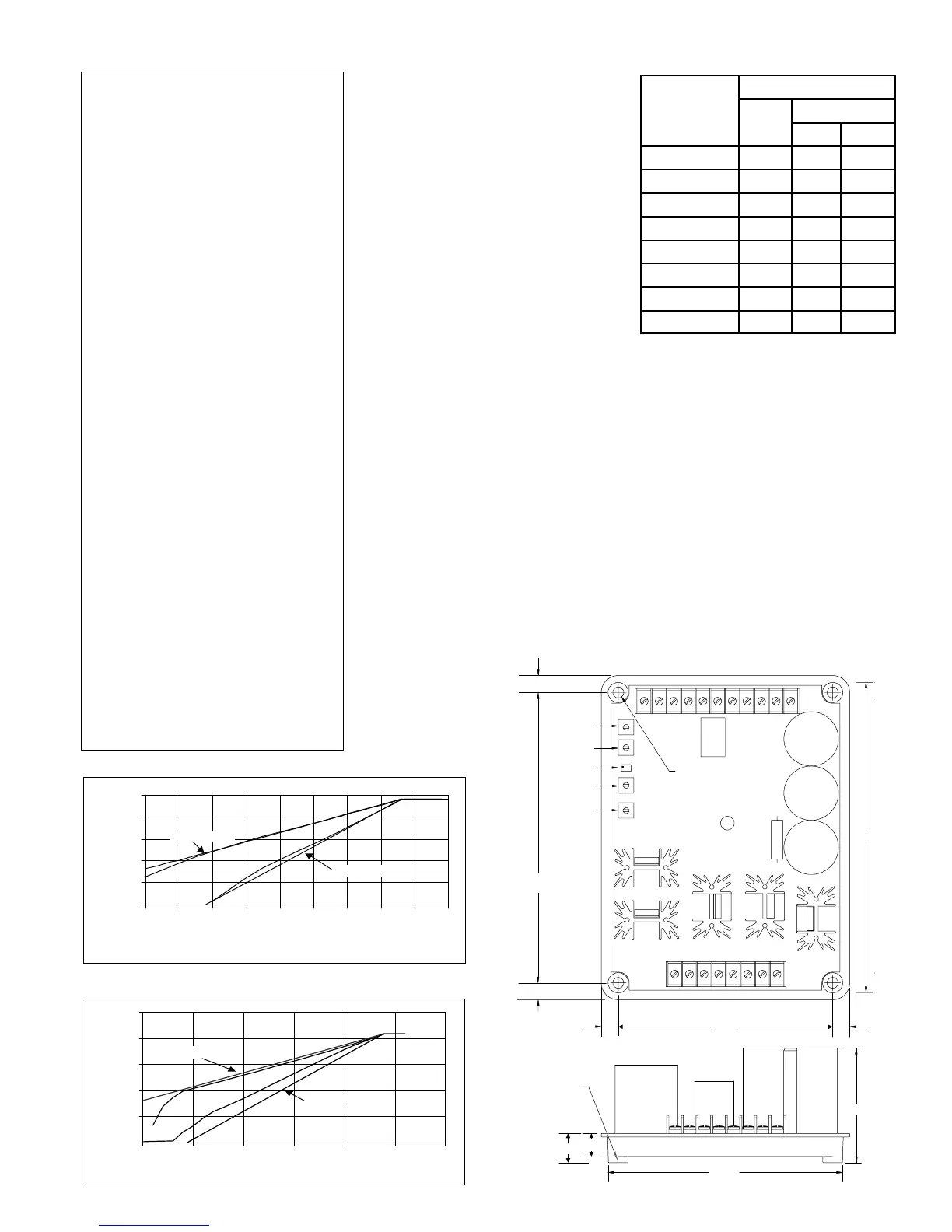
Table 4. Testing Parameters
Input
Sensing
Model Power Vac Freq.
AVC63-12A1 120 120 50/60
AVC63-12A2 120 120 400
AVC63-12B1 120 240 50/60
AVC63-12B2 120 240 400
AVC125-10A1 240 120 50/60
AVC125-10A2 240 120 400
AVC125-10B1 240 240 50/60
AVC125-10B2 240 240 400
0
50
100
150
200
250
20 25 30 35 40 45 50 55 60 65
Frequency In Hertz
Terminal Voltag
Ideal 1 PU/Hz
Ideal 2 PU/Hz
Figure 1. 60 Hertz Frequency Compensation
0
50
100
150
200
250
150 200 250 300 350 400 450
Fre
uenc
in Hertz
Terminal Voltage in Volts
Ideal 2 PU/Hz
Ideal 1 PU/Hz
Figure 2. 400 Hertz Frequency Compensation
5.500
0.593
.281 DIA. HOLE
(4 PL)
6.01
D2590-30.vsd
06-20-01
0.438
STB
VLT ADJ
UF KNEE
FAC CAL
DRP
23455a66a789
F2F1302826242220
0.438
7.500
2.96
0.438
0.438
CH
GND
.750
.51 DIA.
(4 PL)
8.01
Figure 5. Outline Drawing

 Loading...


