9252000991 Rev N BE1-50/51B Controls and Indicators 2-1
SECTION 2 • CONTROLS AND INDICATORS
INTRODUCTION
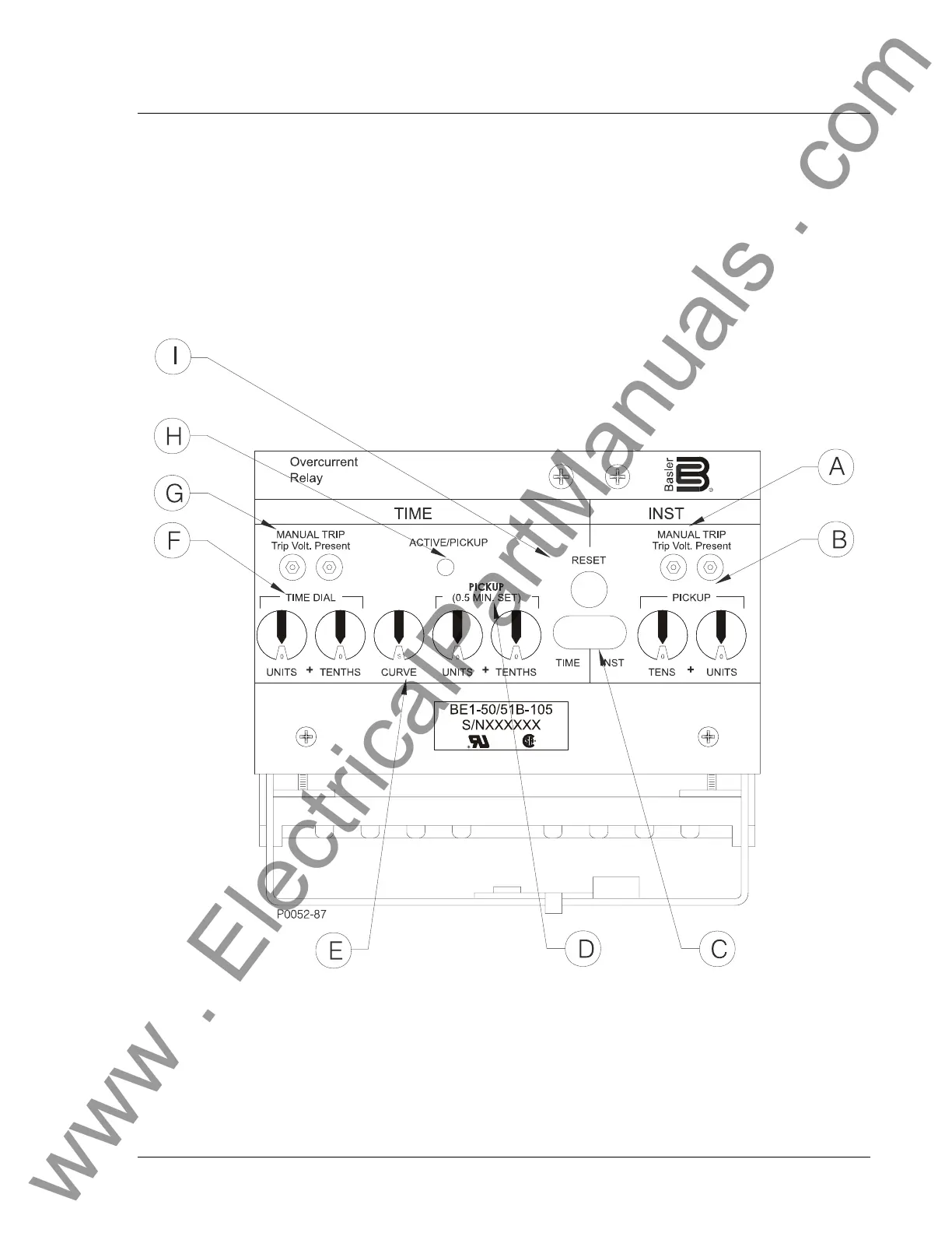
Figure 2-1 illustrates the front panel controls and indicators of the BE1-50/51B. Figure 2-2 illustrates the
location of switch SW3. Both illustrations have lettered call-outs that correspond to the control and
indicator descriptions provided in Table 2-1.
Figure 2-1. Location of Controls and Indicators
www . ElectricalPartManuals . com
 Loading...