4-4 BE1-50/51M - Installation
NOTE
Be sure the ground terminal is hard-wired to the relay panel with no smaller than 12 AWG
copper wire attached to the ground terminal on the rear of the terminal strip.
CONNECTIONS
Incorrect wiring may result in damage to the relay. Be sure to check model and part number before connecting
and energizing a particular relay.
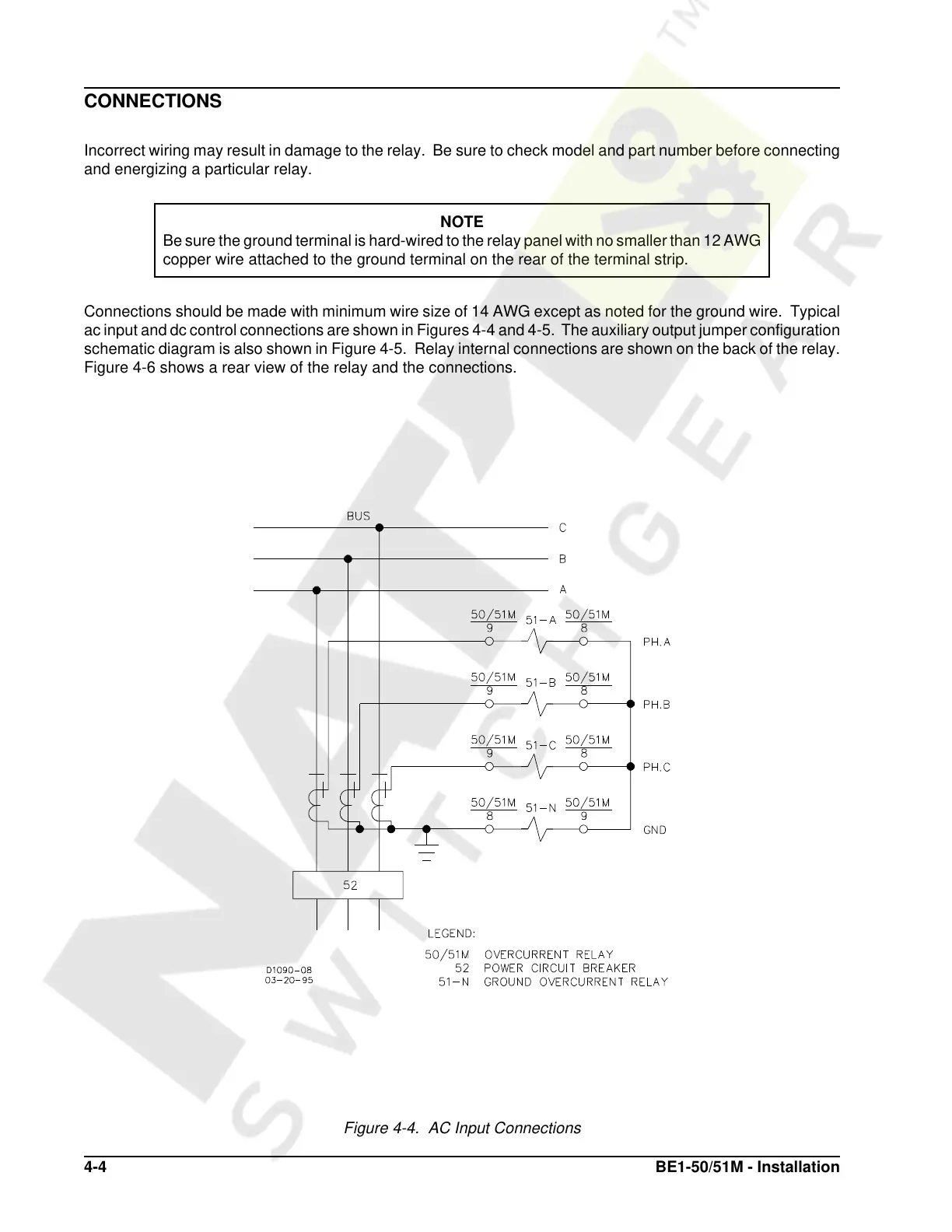
Connections should be made with minimum wire size of 14 AWG except as noted for the ground wire. Typical
ac input and dc control connections are shown in Figures 4-4 and 4-5. The auxiliary output jumper configuration
schematic diagram is also shown in Figure 4-5. Relay internal connections are shown on the back of the relay.
Figure 4-6 shows a rear view of the relay and the connections.
Figure 4-4. AC Input Connections
Courtesy of NationalSwitchgear.com
 Loading...