11
APPLICATIONS
FEATURES
ORDERING INFORMATION
BESTlogic
FUNCTIONAL DESCRIPTIONS
SPECIFICATIONS
BE1-700C
Digital Overcurrent
Protective Relay
PERFORMANCE SPECIFICATIONS
Pickup: 5A CT: 0.50-16.0A
1A CT: 0.10-3.20A
Time Dial: TD=K=0 - 99 for 46 curve
TD=0.0 - 9.9 for all other curves
Time-Current Characteristics:
The following expression describes the inverse time current
characteristic for each curve:
T
T
= AD + BD + K = Time to trip
M
N
-C
T
R
= RD = Time for decaying reset
M
2
-1
where D = Time dial, M = Multiple of PU and A, B, C, N, K
and R are constants that govern the shape of each curve. The
protection engineer can set the constants for the P (programmable)
curve to achieve virtually any characteristic.
BREAKER FAILURE
(BF)
Time: 50-999 mSec
Dropout: 5A CT: 0.5A
1A CT: 0.1A
Time Accuracy: ±0.5% or +1
1
/
4
cyc/ -
1
/
2
cyc
GENERAL PURPOSE LOGIC TIMERS
(62, 162)
Mode: PU.DO
1 Shot, Non-Retrig.
1 Shot, Retrig.
Integrating
Latch
T1 and T2 Delay Time: 0.000 - 9999 sec.
Time Accuracy: ±0.5% or ±
3
/
4
cyc
RECLOSER
(79) (Optional)
Mode: Power up to close, Power up to lockout
Reclose Shots: 0 – 4
Reclose, Reset,
Fail, Max.
Cycle Timers: 0.100 – 600 Sec.
Time Accuracy: +
0.5% or + 1
3
/
4
cyc/-0 cyc
CURRENT PICKUP ACCURACY
Phase and Neutral: 5A: 2% or 50mA
1A: 2% or 10mA
Negative Sequence: 5A: 3% or 75mA
1A: 3% or 75mA
SETTING GROUPS
Setting Groups: 2
Control Modes: Automatic: CLP; Dynamic load or
unbalance
External: Discrete Input Logic;
Binary Input Logic
METERING
Current Range: 5A: 0.5 to 15.0; 1A: 0.1 to 3.0
Current Accuracy: ±1%
DEMANDS
(IA, IB, IC, IN, IQ)
Demand Interval: 1 - 60 min.
Demand Mode: Thermal
BREAKER MONITORING
Duty Mode: I or I
2
Duty Alarm Range: 0-100%
Op Counter Alarm Range: 0-99999
Trip Time Alarm Range: 20-1000 mSec
Pickup:
PU time with TD=0.000 Sec
Delay Time:
Time Accuracy:
5A CT: 0.5-150.0A
1A CT: 0.1-30.0A
2 cyc for P&N @ 5 x PU
3 cyc for Q @ 5 x PU
0.000 - 60 sec
±0.5% or ±
1
/
2
cyc for P&N
±0.5% or ±1 cyc for Q
INSTANTANEOUS OVERCURRENT WITH
SETTABLE DELAY
(50TP, 150TP, 50TN, 150TN, 50TQ, 150TQ)
TIME OVERCURRENT
(51P, 51N, 51Q, 151N)
Available on e-catalog CD,
online at www.basler.com,
or from your representative
GUIDEFORM SPECS
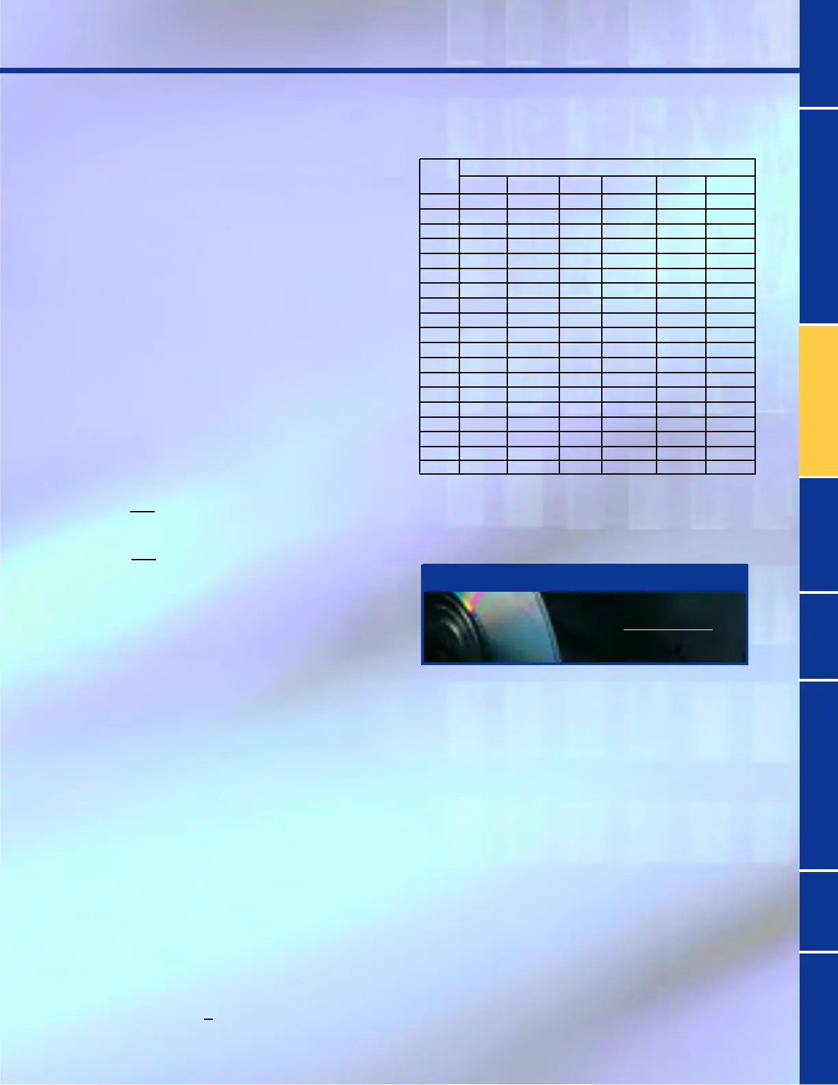
Curve
Type A B C N K R
S1 0.2663 0.03393 1.000 1.2969 0.028 0.5000
S2 0.0286 0.02080 1.000 0.9844 0.028 0.0940
L1 5.6143 2.18592 1.000 1.000 0.028 15.750
L2 2.3955 0.00000 1.000 0.3125 0.028 7.8001
D 0.4797 0.21359 1.000 1.5625 0.028 0.8750
M 0.3022 0.12840 1.000 0.5000 0.028 1.7500
I1 8.9341 0.17966 1.000 2.0938 0.028 9.0000
I2 0.2747 0.1042 1.000 0.4375 0.028 0.8868
V1 5.4678 0.10814 1.000 2.0469 0.028 5.5000
V2 4.4309 0.0991 1.000 1.9531 0.028 5.8231
E1 7.7624 0.02758 1.000 2.0938 0.028 7.7500
E2 4.9883 0.0129 1.000 2.0469 0.028 4.7742
A 0.01414 0.00000 1.000 0.0200 0.028 2.0000
B 1.4636 0.00000 1.000 1.0469 0.028 3.2500
C 8.2506 0.00000 1.000 2.0469 0.028 8.0000
G 12.1212 0.00000 1.000 1.000 0.028 29.000
F 0.0000 1.00000 0.000 0.0000 0.028 1.0000
46
*
0 0 2 0.028 100
P 0 to600 0 to25 0 to1 .5 to 2.5 0.028 0 to 30
Constants
S1, S2 = CO Short Inv, IAC Short Inv A = IEC Standard Inverse
L1, L2 = CO Long Inv, IAC Long Inv B = IEC Very Inverse
D = CO Definite Time C = IEC Extremely Inverse
M = CO Moderately Inverse G = IEC Long Time Inverse
I1, I2 = CO Inverse, IAC Inverse F = Fixed Time
V1, V2 = CO Very Inv, IAC Very Inv 46 =
Neg. Sequence Overcurrent
E1, E2 = CO Ext Inverse, IAC Ext. Inverse P = Programmable

 Loading...


