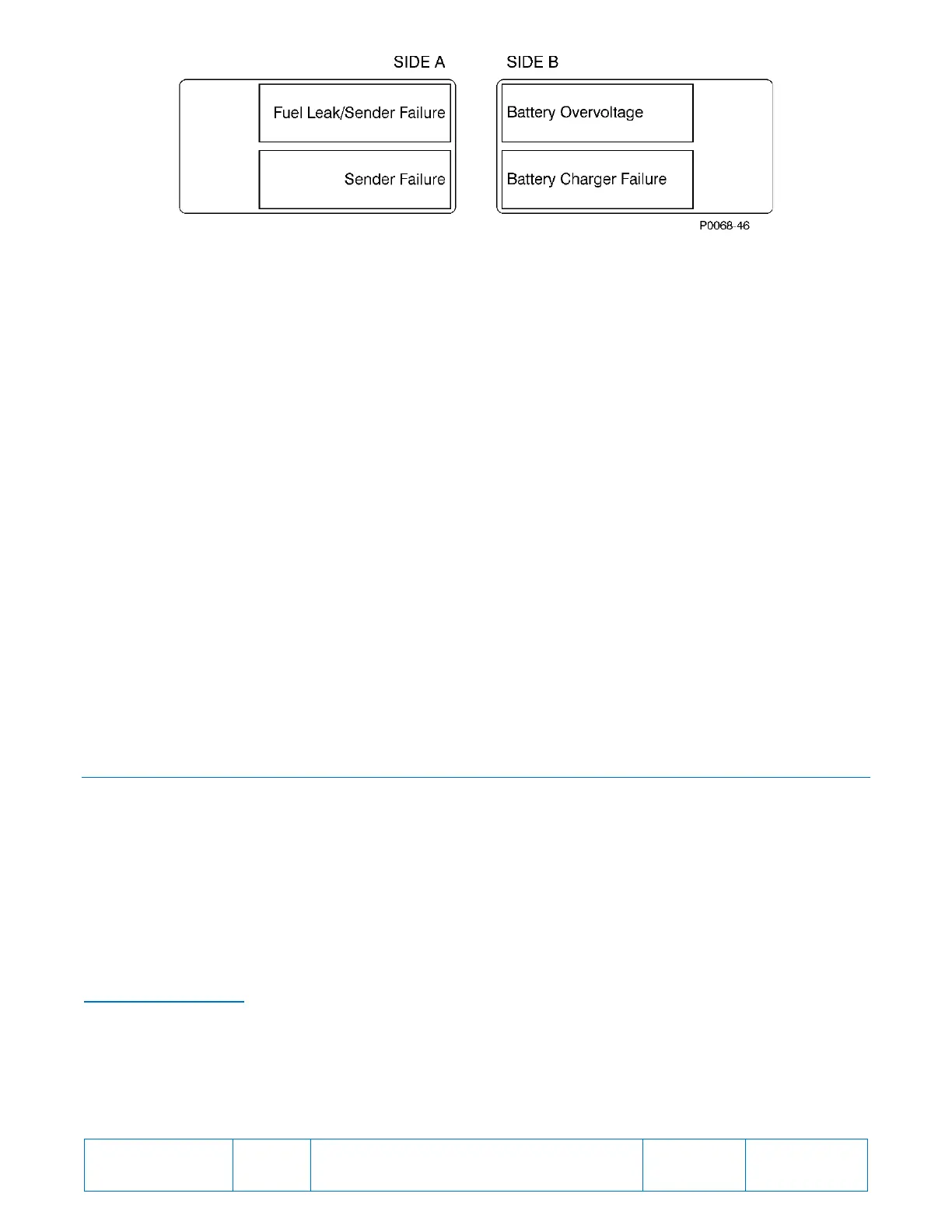
Figure 4. Programmable Alarm and Pre-Alarm Label Cards
Information about configuring DGC logic to provide other alarm and pre-alarm annunciations is available in the
appropriate DGC instruction manual. To relabel the RDP-110C programmable alarm and pre-alarm LEDs,
perform the following steps.
1. Print the label text on readily-available address label sheets. The label cards accommodate adhesive-
backed labels measuring 0.25 by 1.5 inches. Brady
®
B33-45-423 or similar is suitable for this purpose.
2. Remove all control power from the RDP-110C.
3. Remove the four Phillips screws from the front panel and separate the front panel from the conduit box.
Disconnect the connector attached to the circuit board mounted to the front panel. When handling the
front panel, avoid touching the circuit board.
4. Lay the front panel face-down on a suitable work surface.
5. Grasp the tab of the label card to be changed and pull it free. The two label cards are located near the
two lower corners of the circuit board. When facing the back of the panel, the pre-alarm label card is on
the left and the alarm label card is on the right.
6. Apply the labels created in step 1 to the label cards. The rectangle outlines on each label card serve as
guides for attaching the labels.
7. After applying the new labels, insert each label card into the appropriate panel slot. Ensure that each
label card is oriented properly by viewing the custom labels through the label windows of the front panel.
8. Move the panel assembly adjacent to the conduit box and reconnect the cables to the two circuit board
connectors.
9. Secure the front panel to the conduit box with the four Phillips screws removed in step 3. Maximum
torque for these screws is 17 inch-pounds or 2 newton meters.
10. If desired, verify the function of the reprogrammed indicators before returning the RDP-110C to service.
INSTALLATION
A NEMA 1 enclosure makes the RDP-110C resistant to moisture and dust infiltration. Its metal construction
improves immunity to electromagnetic interference. Conduit knockouts on the case enable the RDP-110C to be
used as a “pass-through” or junction box for other site wiring. Two available mounting configurations provide the
option of semi-flush mounting or surface (projection) mounting.
If the RDP-110C will not be installed immediately, store it in the original shipping package in a moisture- and dust-
free environment.
Mounting
RDP-110C mounting dimensions are illustrated in Figure 5, Figure 6, and Figure 7. Dimensions ae shown in
inches with millimeters in parenthesis.
RDP-110 Replacement
An optional adaptor plate (P/N 9318100009) is available for replacement of an RDP-110 with an RDP-110C. The
replacement process is as follows.
1. Remove the RDP-110C front panel from its enclosure and attach it to the adaptor plate using the same
screws removed from the RDP-110C.
2. Remove the RDP-110 from its enclosure and secure the RDP-110C and adaptor plate assembly to the
RDP-110 enclosure using the screws removed from the RDP-110.