Typical Connections
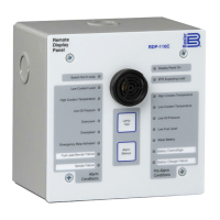
Typical RDP-110C connections are shown in Figure 10.
Figure 10. Typical Connections
TESTING
A built-in test mode enables field testing of RDP-110C operation.
Test Equipment and Setup
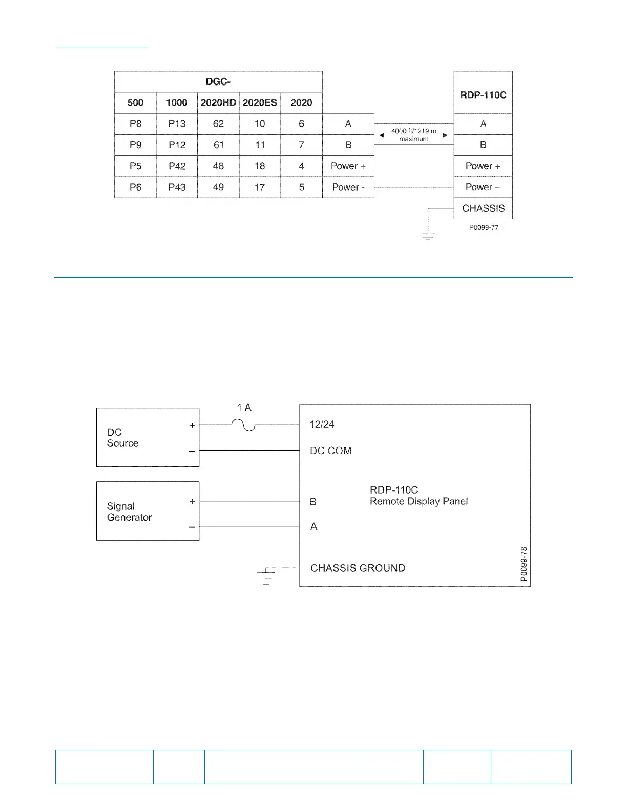
Equipment needed for testing RDP-110C operation is listed below. Connections for the test are illustrated in
Figure 11.
• Power supply, 24 Vdc
• Fuse, 1 ampere
• Signal generator, 10 Hz, square wave, 5 volts peak-to-peak
Figure 11. RDP-110C Test Setup
Test Procedure
1. Connect the RDP-110C test setup as shown in Figure 11.
2. Apply 24 Vdc control power. The Display Panel On LED should light.
3. Press and hold the Lamp Test pushbutton. All LEDs should light and the horn should sound.
4. Release the Lamp Test pushbutton to reset the indicators and horn.
5. Apply the 10 Hz signal.
6. Press and release the Lamp Test pushbutton. Observe that the LEDs and horn annunciate in the
following sequence. This sequence will repeat until the Alarm Silence pushbutton is operated.