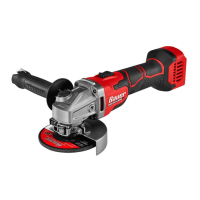
Page 12 For technical questions, please call 1-888-866-5797. Item 57003
Specifications
Electrical Rating 120VAC / 60Hz / 15A
No Load Speed 8500/min
Max. Accessory Diameter 7″ (180mm)
Max. Accessory Thickness 0.3"
Arbor Hole Diameter 5/8"
Spindle Thread 5/8″ - 11 TPI
Setup - Before Use:
Read the ENTIRE IMPORTANT SAFETY INFORMATION section at the beginning of this
manual including all text under subheadings therein before set up or use of this product.
TO PREVENT SERIOUS INJURY FROM ACCIDENTAL OPERATION:
Turn the Power Switch of the tool off and unplug the tool from its electrical
outlet before assembling or making any adjustments to the tool.
Note: For additional information regarding the parts listed in the following pages,
refer to the Assembly Diagram near the end of this manual.
ASSEMBLY
Installing the Wheel Guard
TO PREVENT SERIOUS INJURY: Do not operate this tool without the Wheel Guard properly installed.
Gear
Housing
Wheel
Guard
Wheel Guard
Collar Lock Lever
Grinding
Wheel
1. Unlock the Wheel Guard Collar Lock Lever.
2. Slide the collar of the Wheel Guard
over the rim of the Gear Housing.
3. Rotate the Wheel Guard as needed to
shield you during the planned work.
4. Lock the Wheel Guard Collar Lock Lever securely.
5. Check the Wheel Guard to ensure
it is firmly in place. Adjust if
necessary before proceeding.
SAFETY OPERATION MAINTENANCESETUP