Page 7;&(%$*4.8"4,7%<'*#$"&8#=%/7*,#*%4,77%>?@@@?@AA?BCDC1Item 57610
EF;6GHIJ6KFGLIMNFLMG6MFMO6 E6GPJ
E*$%P/%L8#$('4$"&8#
K*,9%$.*%6MGLK6%LNJIKGFMG%EF;6GH%LMEGKPOGLIME%#*4$"&8%,$%$.*%+*3"88"83%&2%$."#%5,8',7%
"847'9"83%,77%$*Z$%'89*(%#'+.*,9"83#%$.*(*"8%+*2&(*%#*$%'/%&(%'#*%&2%$."#%/(&9'4$1
M&$*- For additional information regarding the parts listed in the following pages,
refer to the Assembly Diagram near the end of this manual.
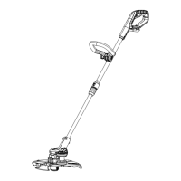
F##*5+7V%
L8#$,77%E,2*$V%R',(9
1. CAUTION! TO PREVENT ACCIDENTAL
CUTS: Cover Line Cutter with a blade
cover before installing the Guard.
2. Remove Screw from bottom of
Trimmer Head. See below.
G("55*(%
e*,9
3. Attach Safety Guard to Trimmer Head
so that the Guard slides into the
corresponding slots on the Head.
4. Turn Trimmer upside down and secure Safety Guard
onto Trimmer Head with the Screw. See below.
E,2*$V%
R',(9
T"8*%
O'$$*(
L8#$,77%e,897*
1. Remove Handle Lock Knob from Handle.
2. Place Handle onto Handle Bracket.
3. Secure Handle to Bracket by placing Lock Knob
and Lock Screw through Handle and Bracket.
e,897*
S(,4W*$
f8&+
4. To adjust Handle, manually move Handle forward
or backward between 5 different locking positions.
1
2
3
4
5
5. To secure Handle, tighten Lock Knob.
Make sure that Handle is in desired
position before tightening fully.