EasyManua.ls Logo

Bauer 2322A-B - User Manual

Bauer 2322A-B
12 pages
Print Icon
To Next Page IconTo Next Page
Loading...
Visit our website at: http://www.harborfreight.com
Email our technical support at: productsupport@harborfreight.com
2322A-B
UNIVERSAL
LATHE
STAND
70595
Owners Manual & Safety Instructions
Save This Manual Keep this manual for the safety warnings and precautions, assembly,
operating, inspection, maintenance and cleaning procedures. Write the product’s serial number in the
back of the manual near the assembly diagram (or month and year of purchase if product has no number).
Keep this manual and the receipt in a safe and dry place for future reference. 23e
When unpacking, make sure that the product is intact
and undamaged. If any parts are missing or broken,
please call 1-888-866-5797 as soon as possible.
Copyright
©
2023 by Harbor Freight Tools
®
. All rights reserved.
No portion of this manual or any artwork contained herein may be reproduced in
any shape or form without the express written consent of Harbor Freight Tools.
Diagrams within this manual may not be drawn proportionally. Due to continuing
improvements, actual product may differ slightly from the product described herein.
Tools required for assembly and service may not be included.
Read this material before using this product.
Failure to do so can result in serious injury.
SAVE THIS MANUAL.
Question and Answer IconNeed help?

Do you have a question about the Bauer 2322A-B and is the answer not in the manual?

Overview

This document provides the owner's manual and safety instructions for the Bauer Universal Lathe Stand, model 2322A-B.

Function Description:

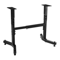
The Bauer Universal Lathe Stand is designed to provide a stable and adjustable base for a lathe. It allows for adjustments in height and length to accommodate various lathe sizes and user preferences, ensuring a comfortable and safe working environment. The stand is intended for supporting a lathe during operation, providing a secure foundation to prevent movement and ensure precision.

Important Technical Specifications:

  • Adjustable Height: 24 1/2" - 34 1/2"
  • Adjustable Length: 23 1/2" - 35 1/2"
  • Weight Capacity: 225 lb

The stand is constructed with various components including mounting platforms, washers, hex bolts, nuts, rubber feet, clips, inner and outer beams, and columns. The assembly process involves attaching the base to the columns, then connecting the outer and inner beams, and finally installing the mounting platforms.

Usage Features:

  • Adjustable Height: The stand's height can be adjusted to suit the user's ergonomic needs. The manual provides instructions on how to determine the proper lathe height, recommending a measurement from the elbow to the floor when the arm is bent at 90 degrees. This measurement helps calculate the ideal mounting platform height for the lathe.
  • Adjustable Length: The stand's length is also adjustable, allowing it to accommodate different lathe sizes. This is achieved by loosening and sliding the inner beam within the outer beam to the desired length, then securing it with hex bolts.
  • Stability: The stand is designed for stability, with rubber feet to prevent slipping and ensure a firm grip on the floor. Proper assembly and tightening of all fasteners are crucial for maintaining stability during use.
  • Universal Design: The "Universal" designation implies that it can support a wide range of lathe models, although users should always verify compatibility with their specific lathe.

Assembly Instructions:

The assembly process involves several steps:

  1. Attaching Feet to Base: Install M12 washers, M12 nuts, and M12 x 100 hex bolts through the top of the base. Then, install M12 large washers, rubber feet, M12 washers, and clips onto the threaded end of the bolt at each end of the base.
  2. Attaching Base to Column: Attach the base to the column using M10 washers and M10 x 80 hex bolts. Secure with M10 nuts.
  3. Attaching Outer Beam to Column: Install M10 washers and M10 x 80 hex bolts through the flange on the outer beam and column. Secure with M10 washers and M12 nuts. Repeat for the other column assembly. The legs on the column base should face outward.
  4. Attaching Inner and Outer Beams: Insert the inner beam into the outer beam. Screw three M10 x 20 hex bolts onto the nuts on the outer beam. Hand tighten the bolts, then secure once the length of the lathe stand has been determined.
  5. Installing Mounting Platforms: Install a mounting platform to the top of each column using M10 washers, M10 x 80 hex bolts, and nuts.
  6. Fastening Lathe to Stand: Securely mount the lathe to the stand using fasteners (not included). Fully tighten all fasteners.

Maintenance Features:

  • Regular Inspection: Before each use, inspect the general condition of the lathe stand. Check for:
    • Loose hardware
    • Misalignment or binding of parts
    • Loose or improper mounting of a tool
    • Cracked or broken parts
    • Any other condition that may affect its safe operation
  • Cleaning: To clean, wipe off the stand with a slightly moist cloth.
  • Problem Correction: If any problems are found during inspection, disconnect the lathe from the power source and correct the problem before further use. If repairs are needed, they should be undertaken by certified and licensed technicians. The manual explicitly states that the manufacturer and/or distributor does not warrant that the buyer is qualified to make repairs.

Safety Information:

The manual emphasizes the importance of reading and understanding all safety messages. It uses various warning symbols:

  • DANGER: Indicates a hazardous situation which, if not avoided, will result in death or serious injury.
  • WARNING: Indicates a hazardous situation which, if not avoided, could result in death or serious injury.
  • CAUTION: Indicates a hazardous situation which, if not avoided, could result in minor or moderate injury.
  • NOTICE/CAUTION (blue box): Addresses practices not related to personal injury.

Key safety precautions include:

  • Assembling only according to instructions.
  • Wearing ANSI-approved safety goggles and heavy-duty work gloves during assembly and use.
  • Keeping the assembly area clean and well lit.
  • Keeping bystanders out of the assembly area.
  • Not assembling when tired or under the influence of alcohol, drugs, or medication.
  • Applying proper weight capacity and other product capabilities.
  • Not exceeding the lathe stand's maximum weight capacity of 225 lb.
  • Being aware of dynamic loading, as sudden load movement may create excess load causing product failure.
  • Using the lathe stand on a flat, level surface capable of supporting the weight of the stand, the lathe, and the workpiece.
  • Turning off and disconnecting power before attaching the lathe to the stand.
  • Following lathe instructions for mounting and operation.
  • Not wearing loose clothing or jewelry, and securing long hair, as they can be caught in moving parts.
  • Wearing protective, electrically non-conductive clothes and non-skid footwear.
  • This product is not a toy.
  • Using as intended only.
  • Inspecting before every use.
  • Maintaining product labels and nameplates.
  • The warnings, cautions, and instructions in this manual cannot cover all possible conditions and situations that may occur.

The manual includes a limited 90-day warranty from Harbor Freight Tools Co., covering defects in materials and workmanship from the date of purchase. It also provides contact information for technical questions.

Bauer 2322A-B Specifications

General IconGeneral
BrandBauer
Model2322A-B
CategoryRacks & Stands
LanguageEnglish