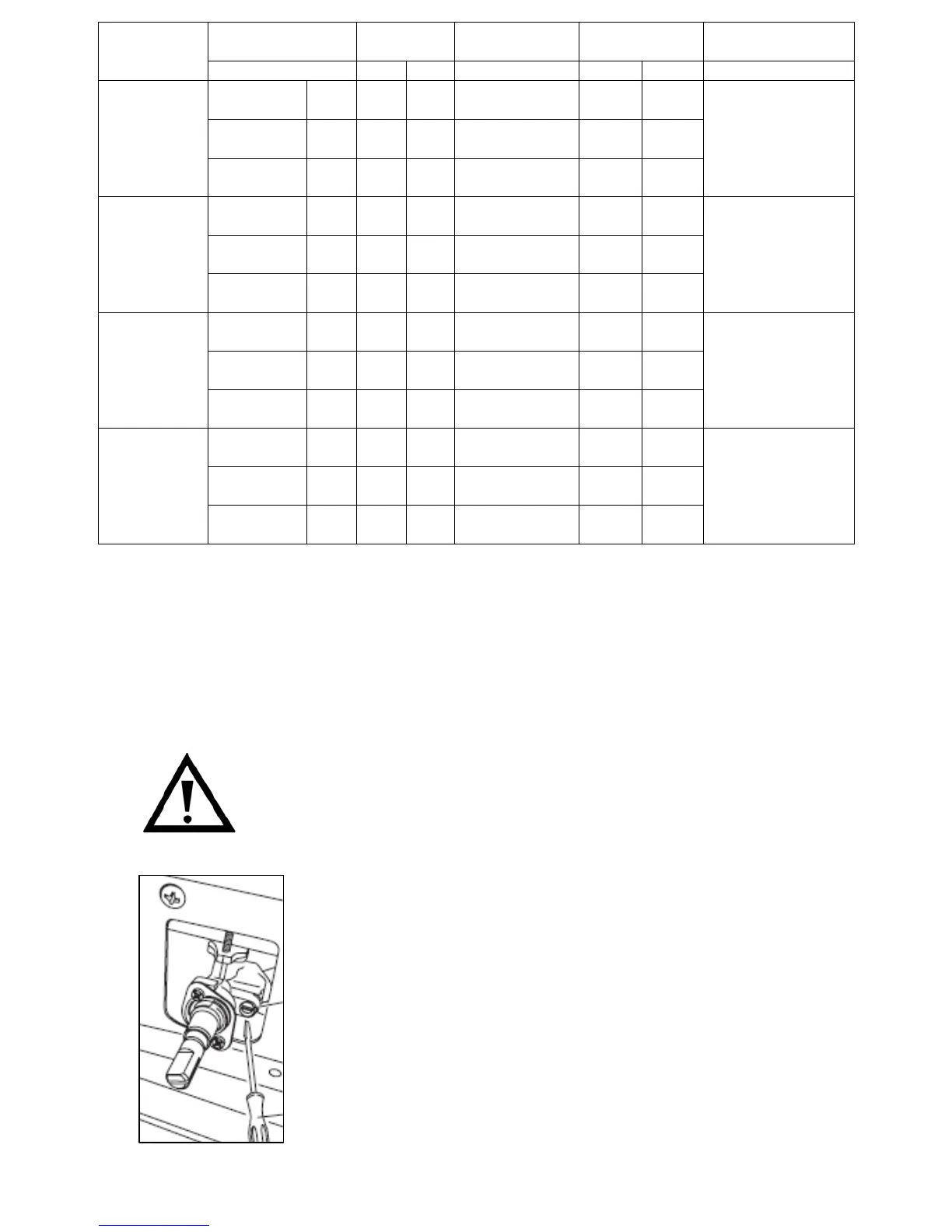
Operating
pressure gas
Rate Diameter
injector
Heat Input
(W)
By-Pass Burner
mbar g/h
L/h
1/100mm Min Max 1/100mm
G30 -
Butane
28 -
30
218
N/A
88 800 3000
G31 -
Propane
37 214
N/A
88 800 3000
Rapid
G20 -
Natural
20 N/A
286
117 - Y 800 3000
44
G30 -
Butane
28 -
30
131
N/A
68 600 1800
G31 -
Propane
37 129
N/A
68 600 1800
Semi -
rapid
G20 -
Natural
20 N/A
171
98 - Z 600 1800
34
G30 -
Butane
28 -
30
73 N/A
51 400 1000
G31 -
Propane
37 71 N/A
51 400 1000
Auxiliary
G20 -
Natural
20 N/A
95 75 - X 400 1000
28
G30 -
Butane
28 -
30
276
N/A
98 1400 3800
G31 -
Propane
37 272
N/A
98 1400 3800
Triple
Crown
G20 -
Natural
20 N/A
362
135 - K 1400 3800
62
o Reassemble all the burners carefully; in particular you should
make sure that the flame spreader is correctly placed on the
burner.
IMPORTANT: After changing the injectors YOU MUST follow the
minimum flow adjustment section below.
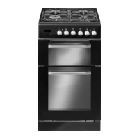
Minimum flow adjustment for hob gas taps.
All work must be carried out by a GASSAFE
registered engineer.
o Light the burner and set the knob at the minimum
position.
o Remove the knob from the tap. The adjustment
screw is located beside the valve body.
o Place a small bladed screwdriver in the centre of
the tap shaft.
o Unscrew the adjusting screw, in order to increase
the gas flow or tighten the adjusting screw to
decrease the gas flow.
35