8
C Pipe adapter for liquid gas (depending on the model)
Only use pipes that comply with Standards. These pipes must be installed so that, when
fully extended, their length does not exceed 2000 mm. To facilitate installation and to
prevent gas leaks, firstly attach the swivel coupling to the cook top and then to the gas
mains pipe. Inverting this sequence may hamper the gas seal between the pipe and the
cook top.
Important: when installation is complete, check that all the couplings are
completely sealed by using a soapy solution. Never use a flame. Also ensure that
the flexible pipe cannot come into contact with any moving part of the cook top
(e.g. drawer) and that it is not in a position where it could be damaged.
After the connection, check the burners for correct operation.
The flames must be clearly visible, and should be blue and green at the center. If
the flame is unstable, increase the minimum power. Explain the use of the burners
to the user and read the instructions for use together.
Adaptation to a different
type of gas
• The procedure or adaptation of the cooker to another type of gas does not require
removal of the appliance from the worktop.
• Before adapting, disconnect the appliance from the power mains and close the gas
supply valve.
• Replace the existing nozzles for nominal thermal load with corresponding nozzles for
the new gas type and supplied provided (see table below).
• After finishing this sequence, replace the old setting label with the new one provided for
the new injectors.
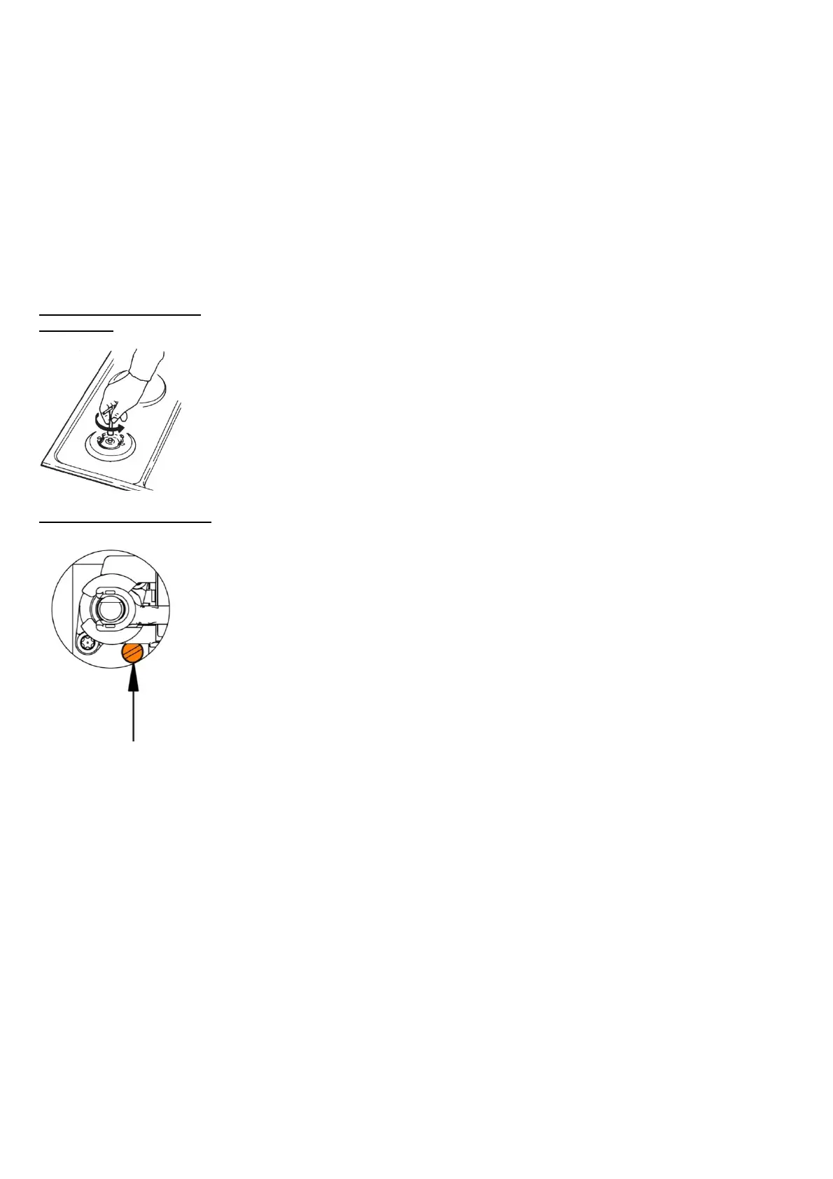
Minimum flow adjustment
Instructions for town (G110, G120, G150.1) and methane gas (G20, G25)
1. Light the burner and bring it to the minimum position.
2. Remove the gas tap knob and turn the adjustment screw on the side of the tap rod,
until a regular minimum flame is obtained:
anti-clockwise to increase the gas flow
clockwise to reduce the gas flow
3. Re-assemble the knob and verify burner flame stability (when quickly rotating the hand
from maximum to minimum position the flame must not shut off).
4. Repeat the operation on all gas taps.
Instructions for liquid gas (LPG: G30, G31)
Tighten the screw on the side of the tap, rod clockwise completely.
• Regulation valves that are factory-built-in are intended for liquid gas; however, the valves are set for operation with the
type of gas for which the appliance is factory-preset.
• When adapting the appliance for use with another type of gas, the regulation screw (valve) should be fastened or release
to correspond with the required gas flow / throughput.
Burner power is indicated by observing the upper Hs caloric value.
Warning: these tasks may only be carried out by a qualified technician, authorized by the gas distributing
company or authorized service center!