Connection diagrams
Operation manual b maXX BM4100 (NWR)
Document no.: 5.04052.09 Baumüller Nürnberg GmbH
76
of 142
7.18
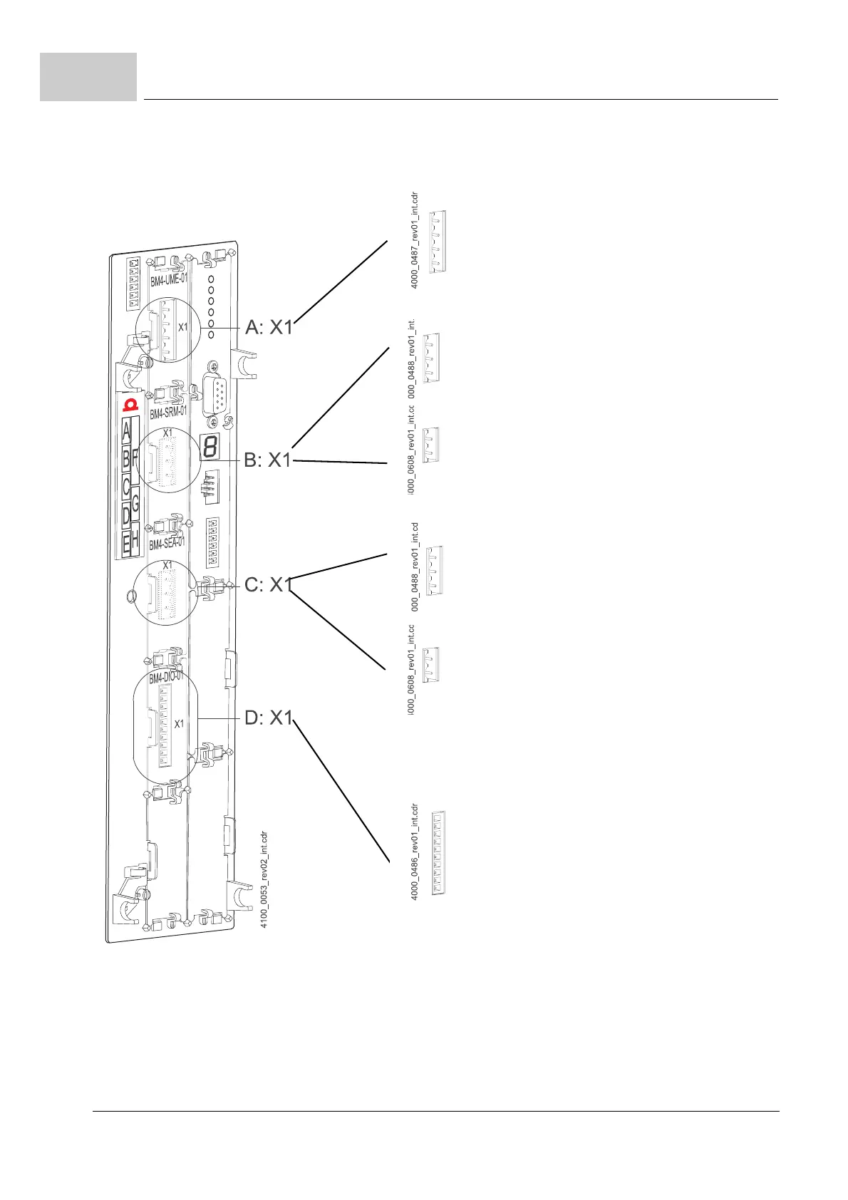
Figure 34: Connections of b maXX BM4100 (NWR)-function modules
BM4-F-UME-01 (slot A)
A: X1-1: L1
A: X1-2: L2
A: X1-3: L3
A: X1-PE: PE
BM4-F-SRM-01 (slot B)
B: X1-1: Monitoring signal of main contactor
B: X1-2: N
B: X1-PE: PE
BM4-F-SRM-02 (slot B)
B: X1-1: Monitoring signal of main contactor
(SELV/PELV)
B: X1-2: M24V (SELV/PELV)
BM4-F-SEA-01 (slot C)
C: X1-1: Coil of main contactor
C: X1-2:N
C: X1-PE:PE
BM4-F-SEA-02 (slot C)
C: X1-1: Coil of main contactor
(SELV/PELV)
C: X1-2: M24V (SELV/PELV)
BM4-F-DIO-01 (slot D)
D: X1-1:Main contactor ON (SELV/PELV)
D: X1-2:
D: X1-3:
D: X1-4:
D: X1-5:Ready for pulse enable (SELV/PELV)
D: X1-6:Power limit reached (SELV/PELV)
D: X1-7:Ready-for-use drive (SELV/PELV)
D: X1-8: Ready for main contactor ON
(SELV/PELV)
D: X1-9:+24 V (SELV/PELV)
D: X1-10:M24 V (SELV/PELV)