Do you have a question about the Baumuller BUG 3 and is the answer not in the manual?
Discusses leakage currents, protective earths, and safety standards for equipment installation.
States the manual is for trained personnel and emphasizes safe operation with state-of-the-art technology.
Defines qualified personnel for setup, assembly, commissioning, and operation.
Specifies that equipment must be used as per instructions and not modified.
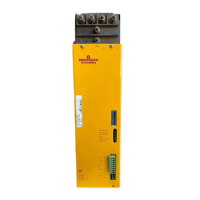
Describes the BAUMOTRONIC converter system and its modular units.
Explains intermediate circuit, power supply, and ballast functions of the drive unit.
Illustrates the internal structure and signal flow of the BUG Basic Unit.
Presents key electrical specifications like voltage, current, power, and temperature ranges.
Details the coding system for identifying different BAUMOTRONIC Basic Feed Unit models.
Provides physical dimensions and mounting hole details for different BUG models.
Gives instructions on unit installation, ventilation, and handling precautions.
Highlights high voltage, rotating parts, and responsibility for safe installation.
Covers measures for ensuring electromagnetic compatibility, including cabling and filtering.
Shows wiring schematics for connecting BUG 3, BUG 2, and BUG 20 units.
Lists terminal assignments for power and control connections on the unit.
Details optional accessories like transformers, ballast resistors, and capacitor units.
Warns about potential uncontrolled motion and safety checks before start-up.
Illustrates the functional relationships between power, ballast, and supply units.
Explains the meaning of system LEDs and possible error messages.
Describes the test connector for diagnostics and message polling.
States units are maintenance-free and prohibits unauthorized modifications.
Provides information on component materials and proper disposal procedures.
Declares compliance with EC-Machine Guidelines for the component.
Certifies conformity with low voltage directive 73/23/EWG.
Outlines terms and conditions related to business and product delivery.
Alphabetical list of topics with corresponding page numbers for quick reference.
| Category | Power distribution unit |
|---|---|
| Model | BUG 3 |
| Frequency | 50/60 Hz |
| Protection class | IP20 |
| Cooling | Natural convection |
| Relative humidity | Up to 95 %, non-condensing |
| Dimensions | Varies depending on configuration |
| Weight | Varies depending on configuration |