Installation Pin Assignments
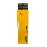
28 BUG 3/2/20 Basic Feed Unit
5.96064.02 Baumüller Nürnberg GmbH
5.4 Pin Assignments
5.4.1 Power Terminals
L1, L2, L3, PE Mains connection (via mains transformer), ground connection
L+ (ZK+)
L- (ZK-) Intermediate circuit connection to the servo power units via the supplied bus-
bars.
Arrange the BUG in the middle of the servo power units.
Wire the intermediate circuit from the BUG 3 and the servo power units with
4 mm² wires.
DANGER
When using autotransformers, the intermediate circuit carries mains poten-
tial; when using isolating transformers, ground L-.
X69 Connection of external ballast (BUG 2 only)
A1, L+ (ZK+) Connection of external ballast (BUG 20 only)
L+ (ZK+), Ballast Connection of external ballast (BUG 3 only)
5.4.2 Control Terminals
Plug-in connection X9 Bus connection to the servo power units.
Supply voltages and operating messages are routed via this connection.
Terminal strip X5
Pin No. Assignment
1 Additional feed via isolating transformer T2 230 V
AC
2 Additional feed via isolating transformer T2 230 V
AC
Terminal strip X1
Pin No. Assignment
1
2
When both contacts close, the system resets stored
messages whose causes are no longer pending
3 Device ground
4 +15 V output
5 -15 V output
6 +24 V output
for controller enables, direction reversal and NP switch
only
7
8
Relay contact (max. of 24 V/1 A) closed on ready-for-
use is pending for 1-2 seconds after mains contactor
closes K1 (SELV)
Terminal strip X2 Connection for test adapter BU (option)