Installation
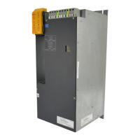
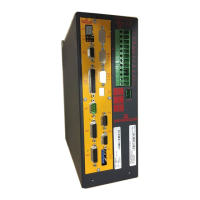
Mono Power Unit BUM 62 T 43
Baumüller Nürnberg GmbH 5.99009.03
Plug-in terminal X99A
Screw connections for cable with wire crimp
1. Position from the top
2. Voltage range (r.m.s. value)
3. Current range (r.m.s. value)
4. Cross-section of the conductor. Observe EMC requirements (see EMC information on page 25)
6. This message only refers to the BUM 62 T, and not to the controller!
(see also ”Ready for operation” on page 53 )
Termina
l
Pos.
1)
Description
U
range
2)
I
range
3)
A
4)
+24 V 1
+ 24 V
DC
(PELV)
5)
Terminals 1 and 2 are bridged internally
24 V +20 %
24 V -10 %
max. 10 A 0.2 -2.5
mm
2
24 - 12
AWG
+24 V 2
M 24 V 3 Ground 24 V
DC
(PELV)
Terminals 1 and 2 are bridged internally
0 V
M 24 V 4
BB
int.
5
Message ”Internal ready for operation"
6)
0 V Supply part is not ready
24 V Supply part is ready
0 V
or
24 V
(PLC level)
-
ZUS. 6 Reserve - -
5.
NOTE
The input of the power supply includes capacitors (250 µF) so that charge current occur when the
24V supply is switched!