Do you have a question about the Baumuller BUM 62 and is the answer not in the manual?
Defines DANGER, WARNING, and NOTE terms for safety.
Defines who is considered qualified personnel for safety.
Specifies unit usage must align with operating instructions.
Outlines requirements and procedures for voltage testing.
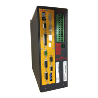
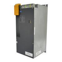
Overview of BUM 62, 63, 64 mono power units and their applications.
Detailed explanation of the functional components of the units.
Illustrates the internal connections and signal flow for BUM 62.
Illustrates the internal connections and signal flow for BUM 63/64.
Lists key electrical specifications, current, voltage, and power ratings.
Explains the coding system used for product identification.
Presents dimensional drawings and key measurements for the units.
Provides essential guidelines for safe and effective unit installation.
Details the mounting and fastening procedures for the units.
Warns about electrical hazards and rotating parts during installation.
Covers relevant standards, protection classes, and environmental conditions.
Discusses electromagnetic compatibility measures and configuration for optimal performance.
Provides guidance on proper cabling techniques to suppress noise.
Explains the principles and methods for effective grounding to meet EMC requirements.
Details methods for effective cable screening for noise reduction.
Discusses the need for and assembly of filters for EMC compliance.
Warns about discharge currents and incompatibility with certain circuit breakers.
Explains the function and necessity of safety relays for preventing unexpected starts.
Details techniques and principles for preventing hazardous unintended machine starts.
Describes safety categories and their relevance to machine components.
Explains the operation and function of the safety relay in fail-safe mode.
Illustrates the operational sequence of the safety relay.
Shows a practical wiring example for safety category 3 applications.
Demonstrates a wiring example for safety category 4 applications.
Provides detailed wiring diagrams for the terminal connections of BUM 62.
Details the terminal connection diagram for the BUM 63 unit.
Presents the terminal connection diagram for the BUM 64 unit.
Explains specific terminal functions and connection notes for fuses, contactors, etc.
Details the pin assignments for power terminals on BUM 62.
Lists pin assignments for power terminals on BUM 63 and BUM 64.
Describes the pin assignments for control terminals, including X99A/X99B.
Explains the function and assignment of terminals on the X99AB sub-unit.
Details the pinout and function of the optional X68 safety relay connector.
Provides connection information for the unit's terminal fan.
Explains the use of the X60 plug for controller cassette connection.
Lists available accessories such as fuses and line reactors.
Provides specifications and dimensions for 400V line reactors.
Provides specifications and dimensions for 500V line reactors.
Lists components available for enhancing EMC performance.
Warns about electrical hazards and rotating parts during commissioning.
Illustrates the operational logic and status indicators for BUM 62.
Shows the operational logic and status indicators for BUM 63/64.
Explains how the controller manages the unit and how to reset faults.
Details various system messages and warnings monitored by the unit.
Describes monitoring functions for mains voltage, phase, and temperature.
Covers monitoring of overcurrent, earth-fault, DC link voltage, and transistor status.
Explains monitoring of the auxiliary voltage supply and error reporting.
Discusses supply monitoring and its relation to the controller cassette.
Explains how cooling element temperature is monitored via the controller.
Defines the "Ready for use" status and its communication.
Describes how to reset stored errors via controller signals.
Explains the optional safety ready function and its states.
Details how the unit responds to voltage failures and automatic restarts.
States that the unit is maintenance-free and prohibits unauthorized conversion.
Advises on proper storage conditions to prevent damage, especially to capacitors.
Instructs on recommissioning procedures, especially after storage.
Outlines the components and materials of the units and disposal guidelines.
Declaration of conformity to EC Machine Directives for the mono power unit.
Declaration of conformity to the Low Voltage Directive for the product.
Outlines the terms and conditions governing sales, deliveries, and warranties.
Details payment terms, due dates, and consequences of late payment.
Explains the retention of ownership until full payment is received.
Defines rights and restrictions related to the unit's software and licensing.
Covers miscellaneous conditions, including validity of terms and gap-filling.
Specifies procedures and responsibilities for goods acceptance.
Outlines conditions for erection and installation services.
Provides an alphabetical index of topics and their corresponding page numbers.
| Brand | Baumuller |
|---|---|
| Model | BUM 62 |
| Category | Portable Generator |
| Language | English |