Commissioning
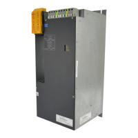
Mono Power Unit BUM 62 T 55
Baumüller Nürnberg GmbH 5.99009.03
7.3.2 Monitoring functions
The following table lists all monitoring functions. An explanation of every individual monitoring function
will be given on the following pages.
1. The V controller always outputs this collective message in the event of an error in the supply part.
The corresponding LED displays on the front of the unit which error has occurred.
2. Trigger reset input (apply +24V and M24V at X99AB, optocoupler input).
or
Switch off +24V supply voltage.
This clears all messages of the supply part!
If you observe the WARNING message, you can bring the drive to a defined operating state before
the power unit clears the ”Supply part ready” message and de-energizes.
3. Not possible via the reset input! For safety reasons you have to wait until the DC link has discharged
(U
ZK
< 20 V), then switch off +24-V supply voltage.
This clears all messages of the supply part!
4. You must clear this message by a controller reset.
The controller documentation specifies how to display and clear the message.
5. A message occurs only if the safety relay is switched off. The safety relay is switched off only if the
+24V supply voltage for the relay is not applied.
Switch on again the +24 V supply voltage for the relay before you can clear the message by a
controller reset.
Monitoring function LED Relay V-
controlle
r
Reset
Supply part Phase failure WARNING
PHASE ERR.
-
X99AB; 3,4
-
F 0110
1)
-
24 V
2)
Mains failure WARNING
POWER ERR.
-
X99AB; 3,4
-
F 0110
1)
-
24 V
2)
Short circuit regenerative
circuit output
BRAKE OVERL.
-
F 0110
1)
U
ZK
3)
power part
on the
motor side
Overcurrent (motor) - -
F 0202
cont.
4)
Earth current (short circuit) - -
F 0203
cont.
4)
Overvoltage DC link
- -
F 0201
cont.
4)
Power transistors
- -
F 0207
cont.
4)
Overheat heat sink
- -
F 0205
cont.
4)
Internal auxiliary voltage
- -
F 0204
cont.
4)
Safety relay
-
X 68; 1,2
5)
F 0206
cont.
4)