This document is an installation, operation, and maintenance manual for the Baxi 11i and Baxi 14i water heaters.
Function Description
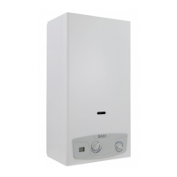
The Baxi 11i and Baxi 14i are instant hot water heaters designed to provide hot water on demand. They are particularly suited for use with mechanical mixers and thermostats due to their modifiable flame. Unlike water heaters with a fixed flame, these models feature a modulation valve that optimizes operation by adjusting the flame according to the amount of water used, maintaining a constant output temperature. This "PROPORTIONAL" automatic variation allows for gas consumption to be changed in response to the extracted water volume.
The device is equipped with an electronic tool powered by a 1.5 V LR20 alkaline battery, which automatically switches on the pilot flame and then the main burner when hot water is extracted. The flame is ignited using a card that ionizes the flame.
Model 11i:
- For water extraction between 2.5 and 5.5 liters per minute (l/m), the water temperature remains at 60°C. In this range, the gas valve supplies the burner with the necessary gas quantity proportional to the water supplied.
- For water extraction above 5.5 l/m up to 11 l/m, the water temperature varies from 60°C down to 40°C.
Model 14i:
- For water extraction between 2.5 and 7 l/m, the water temperature remains at 60°C. In this range, the gas valve supplies the burner with the necessary gas quantity proportional to the water supplied.
- For water extraction above 7 l/m up to 14 l/m, the water temperature varies from 60°C down to 40°C.
The water heater also includes a gas economizing device, activated by rotating knob A to the small flame (MIN) position. This feature limits the amount of heating when hot water usage is modest (e.g., when the supplied water is already warm or during summer), thereby saving gas.
The product is equipped with flue gas release safety devices, ensuring the correct discharge of combustion by-products. These devices monitor the flow of combustible gas to the release conduit and smoke channel. A "thermostat" connected to the electronic devices can stop the gas flow to the main burner or pilot flame if the release conduit or smoke channel is partially or totally obstructed. To reset the device, the flue gas thermostat key must be pressed, and the hot water tap reopened.
Important Technical Specifications
General:
- CE Mark: Conforms to European Directives 142/2009 and 93/68.
- Power Source: 1.5 V LR20 alkaline battery.
- Category: II2H3+ (for IT-ES-PT-F)
- Gas Types: Methane Gas (G20) and Liquid Gas (G30/G31).
- Nominal Feed Pressure: 20 mbar (G20), 28-30 mbar (G30), 37 mbar (G31).
- Water Connections: 1/2".
- Flue Gas Release Tube Diameter: 110 mm (Baxi 11i), 130 mm (Baxi 14i).
- Maximum Water Pressure (P H₂O max): 10.0 bar.
- Relative Cold Water Temperature: 15 °C.
Baxi 11i:
- Nominal Power Usage (Pn): 19.0 kW (16,340 kcal/h).
- Nominal Thermal Range (Qn): 21.8 kW (18,748 kcal/h).
- Minimal Power Usage (Pm): 7.5 kW (6,424 kcal/h).
- Minimal Thermal Range (Qm): 9.0 kW (7,740 kcal/h).
- Consumption: 2.31 m³/h (G20), 1.72 kg/h (G30), 1.69 kg/h (G31).
- Burner Pressure: 12.20 mbar (G20), 27.50 mbar (G30), 35.10 mbar (G31).
- Ø Pilot Flame Nozzle: 0.35 mm (G20), 0.25 mm (G30/G31).
- Ø Main Burner Nozzle: 1.18 mm (G20), 0.71 mm (G30/G31).
- Number of Nozzles: 11.
- Maximum Flue Gas Load: 13.20 g/s (G20), 12.40 g/s (G30), 13.00 g/s (G31).
- Flue Gas Temperature: 185 °C (G20), 180 °C (G30), 182 °C (G31).
- Water Input Range: 2.5 to 10.8 l/min (select. min. da 2,5 a 5, select. max da 5 a 10,8).
- Water Temperature Elevation: Approximately 50 °C (select. min.), Approximately 25 °C (select. max).
- Minimum Pressure: 0.2 bar.
- Nominal Pressure: 2 bar.
- Dimensions (H x L x D): 592 x 314 x 245 mm.
- Weight: 11.10 kg.
Baxi 14i:
- Nominal Power Usage (Pn): 23.7 kW (20,374 kcal/h).
- Nominal Thermal Range (Qn): 27.2 kW (23,392 kcal/h).
- Minimal Power Usage (Pm): 7.5 kW (6,424 kcal/h).
- Minimal Thermal Range (Qm): 9.0 kW (7,740 kcal/h).
- Consumption: 2.88 m³/h (G20), 2.14 kg/h (G30), 2.11 kg/h (G31).
- Burner Pressure: 13.00 mbar (G20), 27.00 mbar (G30), 34.30 mbar (G31).
- Ø Pilot Flame Nozzle: 0.35 mm (G20), 0.25 mm (G30/G31).
- Ø Main Burner Nozzle: 1.18 mm (G20), 0.72 mm (G30/G31).
- Number of Nozzles: 13.
- Maximum Flue Gas Load: 18.40 g/s (G20), 17.70 g/s (G30), 19.00 g/s (G31).
- Flue Gas Temperature: 168 °C (G20), 163 °C (G30), 158 °C (G31).
- Water Input Range: 2.5 to 13.6 l/min (select. min. da 2,5 a 6,7, select. max da 6,7 a 13,6).
- Water Temperature Elevation: Approximately 50 °C (select. min.), Approximately 25 °C (select. max).
- Minimum Pressure: 0.2 bar.
- Nominal Pressure: 2 bar.
- Dimensions (H x L x D): 650 x 363 x 245 mm.
- Weight: 12.60 kg.
Usage Features
Installation:
- Installation must comply with current regulations and be performed by qualified personnel.
- The device should be installed on a suitable wall surface near a fume disposal flue, ensuring minimal distances for maintenance (as shown in Fig. 3).
- Adequate air flow and ventilation are crucial. Permanent openings to the wall leading outdoors or single/collective ventilation ducts are required.
- Indirect ventilation from adjacent areas is permitted under specific conditions (e.g., adjacent area has direct ventilation, devices connected to a waste duct, no bedroom, not a common area, not a fire hazard, and no opposing draught).
- The device is powered by a 1.5 V LR20 battery, eliminating the need for a power socket.
- Gas connection requires blowing out the gas pipe to remove residues and installing a tap above the device.
- Water connection involves inserting a filter into the water valve input fitting and connecting cold water to the right input and hot water to the left output.
- The device is designed for flue gas release and must be connected to a properly working chimney or flue pipe.
- Gas transformation (Methane to LPG or LPG to Methane) can be performed while mounted, but only by qualified personnel. This involves substituting pilot and burner injectors, and the modulation valve, followed by gas adjuster regulation.
Operation:
- To use, ensure the main gas supply tap and all water taps are switched on.
- Open the gas tap (not supplied) placed immediately before the water heater.
- Rotate knob A towards the large flame (ON) position. When the small flame is reached, press lightly while turning to reach the destination.
- When hot water is requested, the device automatically turns on the pilot flame, which then lights the main burner.
- When hot water request terminates (water tap off), the burner automatically switches off.
- If the device does not function within 60 seconds, the flame detector interrupts the gas flow and blocks the device. To reuse, close and reopen the hot water extraction tap.
- If the main burner accidentally switches off, the device will attempt to turn on again.
- The temperature selector (knob B) allows for adjusting water output: rotate left for maximum output, right for minimum output.
- The machine is switched off by rotating knob A to the (OFF) position.
- For prolonged periods of non-use, close the gas supply tap or LPG gas valve.
- In case of freezing risk (temperatures below 0°C), the device must be emptied of all water.
Maintenance Features
- Annual maintenance checks by qualified personnel are recommended to ensure maximum efficiency and safety.
- Before cleaning or maintenance, switch off the device and turn off the gas supply.
- Maintenance operations include:
- Removing any rust from the burner.
- Removing any deposit on the glow plug by the electrode.
- Cleaning the combustion tank.
- Checking ignition, switching off, and general functionality.
- Checking that gas and water tubes and connections are sealed.
- Checking the main burner, pilot flame, ignition electrode, and safety valve.
- Ensuring no obstructions in the exchanger smoke channel.
- The exterior panels can be cleaned with a cloth and soapy water.
- Prohibited actions:
- Using solvents, powders, or abrasive sponges for cleaning.
- Cleaning the device or its parts with flammable materials (e.g., petrol, alcohol, diesel).
- Attempting repairs by unauthorized technicians.
- Modifying or removing the flue gas release safety device. Only qualified technicians authorized by the manufacturer can check or substitute it, using "original parts" supplied by the manufacturer.
Troubleshooting (Problems and Solutions):
- No spark:
- Exhausted battery: Substitute.
- Electrical cable disconnected: Insert.
- Electrical card broken: Test, substitute.
- Insufficient water pressure: Repair device, rotate selector knob right.
- Pilot does not switch on with spark:
- Membrane broken: Substitute.
- Electrode damaged: Substitute.
- Safety device broken: Substitute.
- No gas supply: Open gas tap.
- Air in gas tubes: Release gas.
- Burner does not switch off when water turns off:
- Grime on gas shutter: Test, clean.
- Valve piston/stem locked open: Disassemble, clean, substitute.
- Micro lever locked open: Test.
- LPG supply, check gas pressure: Regulate, substitute tank pressure regulator if necessary.
- Exchanger blade dirty quickly:
- Poor draught/dusty surroundings: Check smoke channel efficiency.
- Yellow flame: Check gas type, clean burner.
- Excess gas consumption: Check and regulate.
- Smell of gas:
- Gas loss in tubes: Check tubes, find leak. Do not activate electric switches or objects that produce sparks.
- Obstruction in flue gas circuit: Check smoke channel and flue gas conduit efficiency.
- Excess gas consumption: Check and regulate.
Removing the Casing:
- Remove selector knobs (A and B).
- Remove screws (C).
- Shift casing upwards, then forwards.
- Reinsert in reverse order.