6
2. INSTALLATION
2.a Regulations
The use of gas devices is controlled by precise regulations.
It is essential to observe regulations in force.
Installation of liquid petroleum gas (L.P.G) must comply with all the
distributor’s requirements and those of the regulations.
2.b Wall mounting
Warning
Do not install this device in an area that contains dust, greasy va-
pour and/or corrosive elements.
- The device must be installed on a suitable wall surface in proxi-
mity to a fume disposal ue
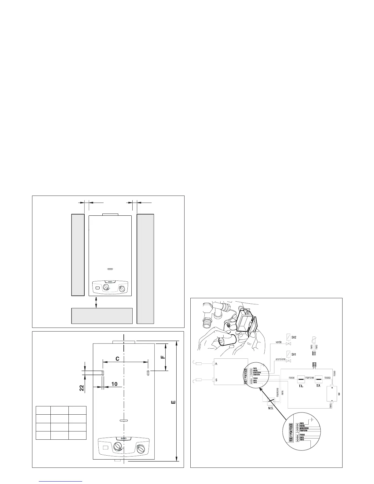
- It is vital to leave the minimal distances around the device as
shown in g 3 to allow for maintenance operations to take place.
Location
The water heater must not be tightly placed in an enclosure or slot,
it should have an adequate ow of air around it
- The water heater must not be placed above a kitchen or other
cooking devices that might deposit grease vapour on its exterior
leading to corrosion
- Surfaces that sensitive to heat (e.g. wood) must be protected
using appropriate insulation.
- Fig. 4 displays the dimensions necessary for wall mounting
2.c Room ventilation
The installation of the water heater must comply with regulations in
force including any updates. See paragraph 2.a
Warning: This device can only be installed in venues that are per-
manently ventilated according to regulation in force.
Air circulation
It is vital that areas where gas devices are installed (type B) have
access to the amount of air necessary for the regular combustion
of gas as well as the ventilation of the venue.
- It is prohibited to use an extractor fan, replaces and other simi-
lar devices at the same time as the water heater
- The area where the water heater is installed must have a regular
ow of air for ventilation.
Air ow
The ow of air must occur by the following means:
- Permanent openings in the wall that lead outdoors
- Single or collective ventilation ducts.
The air used for ventilation must be taken directly from an outside
location, that is far from sources of pollution.
Indirect ventilation from adjacent areas are permitted with the fol-
lowing limitations:
- The adjacent area is equipped with direct ventilation
- The devices within the area to ventilate are connected to a waste
duct
- The adjacent area does not contain a bedroom and is not a com-
mon area;
- The adjacent area is not a re hazard such as a storage area for
ammable materials, garage etc.
- The adjacent area is not lower than the area to ventilate as this
might lead to an opposing draught (this can be caused by other
devices that operate on the basis of combustion, a replace or
any suction device that have not been given an adequate air
supply)
- The air ow from the adjacent area occurs freely through perma-
nent openings.
2.d Electrical connection to battery
The device is powered by a 1.5 V battery, alkaline long lasting mo-
del LR20, thus it is not necessary to connect the device to a power
socket.
Fig. 3


 To Next Page
 Loading...