12
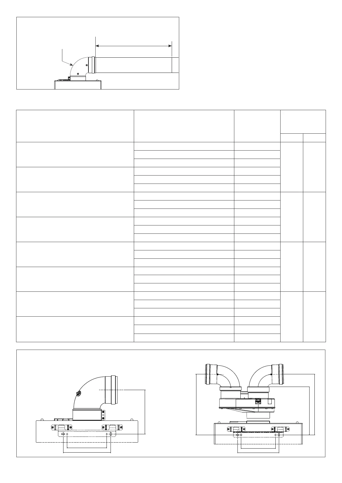
Fig. 11 - Discharges dimensions
Reference table for maximum workable length based on the selected exhaust type
266
150
180
266
210
AS
SC
160
180
150
COAXIAL DISCHARGES
SPLIT DISCHARGES
Length pipes/metres
Maximum considered length
The 90° appliance output
curve load loss should
NOT be calculated
Maximum pipe length (see following table)
Exhaust type
Length
pipes/metres
Excluding the 90° appliance output curve
Refer to g. 10
Fume
ange (mm)
The fume ange,
when necessary, must
be removed using a
screwdriver as a lever
Load loss
for each
additional curve
45° 90°
TYPE B22
Open chamber and forced draught for indoor
14Fi AM Blue
up to 7 ø 45
1,3 m 1,8 m
from 7 to 13 ø 47
from 13 to 25 not installed
TYPE B22
Open chamber and forced draught for indoor
17Fi AM Blue
up to 4 ø 46
from 4 to 8 ø 48
from 8 to 12 not installed
TYPE C - TYPE B32
Horizontal coaxial exhausts
14Fi AM Blue
up to 1 ø 45
1 m 1,4 m
from 1 to 1,9 ø 47
from 1,9 to 3,7 not installed
TYPE C - TYPE B32
Horizontal coaxial exhausts
17Fi AM Blue
up to 1 ø 46
from 1 to 1,6 ø 48
from 1,6 to 3,2 not installed
TYPE C
Vertical coaxial exhausts
14Fi AM Blue
up to 2 ø 45
1 m 1,4 m
from 2 to 2,9 ø 47
from 2,9 to 4,7 not installed
TYPE C
Vertical coaxial exhausts
17Fi AM Blue
up to 2 ø 46
from 2 to 2,6 ø 48
from 2,6 to 4,2 not installed
TYPE C
Split exhausts
14Fi AM Blue
5+5 ø 45
1,3 m 1,8 m
from 5+5 to 9,5+9,5
ø 47
from 9,5+9,5 to 17+17
not installed
TYPE C
Split exhausts
17Fi AM Blue
3+3
ø 46
from 3+3 to 6+6
ø 48
from 6+6 to 9+9
not installed
Fig. 10 - Maximum pipe length
 Loading...