This document provides installation and servicing instructions for the Baxi Arena Super and Baxi Baroque Super living flame effect gas fires, designed for use with natural gas.
Function Description
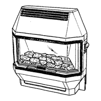
The Baxi Arena Super and Baxi Baroque Super are living flame effect gas fires that provide heat and ambiance. They operate on natural gas and feature electronic ignition to light the pilot. The fires are controlled by a knob with six positions, offering four output settings: OFF, PILOT, LOW, MEDIUM, and HIGH. Additionally, the artificial coal bed can be illuminated by concealed bulbs, operated by a switch located below the control knob, independently of whether the fire is on or off. These fires are suitable for both hearth and wall mounting.
Important Technical Specifications
General Specifications (Baxi Baroque Super & Baxi Arena Super):
- Heat Input (High): 5.57 kW (19,000 Btu/h)
- Heat Input (Med-High): 4.84 kW (16,500 Btu/h)
- Heat Input (Med): 3.22 kW (11,000 Btu/h)
- Heat Input (Low): 2.11 kW (7,200 Btu/h)
- Heat Output (High): 3.40 kW (11,590 Btu/h)
- Gas Connection: Rc½ (¼in BSPT Internal)
- Electricity Supply: 230V~50Hz 120W, External fuse - 3A
- Controls: Rotary gas tap with oxy-pilot device, Electronic ignition of pilot.
- Gas Rate (after 10 mins): 0.53m³/h (18.7ft³/h)
- Setting Pressure (Cold): 14.0 ± 0.5 mbar (5.6 ± 0.2 in wg)
- Thermocouple Output: 9.4 - 13mv
Baxi Baroque Super Specifics:
- Lifting Weight: 27.0 kg (59.5 lbs)
- Outercase Dimensions: Height 689mm, Width 703mm, Depth 337mm
Baxi Arena Super Specifics:
- Lifting Weight: 27.0 kg (59.5 lbs)
- Outercase Dimensions: Height 689mm, Width 680mm, Depth 323mm
Site Requirements:
- Fireplace Opening: Minimum 100mm (4in) deep at flue spigot height. Minimum 412mm (16 7/32in) between base of opening and bottom of flue spigot.
- Fireplace Surface: Non-combustible, flat vertical surface measuring 765mm (30 1/8in) wide x 765mm (30 1/8in) high around the opening.
- Hearth Mounting: Non-combustible material, at least 13mm (1/2in) thick, 340mm (13 3/8in) deep by 830mm (32 5/8in) wide. Minimum 50mm (2in) above floor level. Not to be fitted directly onto combustible floor/carpet.
- Wall Fixing: Wall must be non-combustible, base of fire no less than 75mm (3in) above floor level.
- Shelf above fire: At least 100mm (4in) above canopy, not more than 229mm (9in) deep.
- Chimney: Must be swept if previously used for solid fuel. At least 3.10m (10ft) high. Must not be cracked, serve one room only, not joined with voids, not blocked, have positive flue pull, and have standard 229mm x 229mm (9in x 9in) section or 127mm (5in) flue liner.
- Pre-Cast Flues: Suitable for properly designed and constructed pre-cast flues complying with BS 1289. Flue must be at least 3.10m (10ft) high with a flue way of at least 197mm x 67mm (7 3/4in x 2 5/8in) or equivalent cross-sectional area. Mortar must not obstruct flue way.
- Electrical Supply: Earthed, 230V ~ 50Hz, fused at 3A. Connection via fused three-pin plug and unswitched shuttered socket outlet (BS 1363) or fused double-pole isolator with 3mm (1/8in) contact separation.
Usage Features
- Control Knob: Provides six positions for output settings: OFF, PILOT, LOW, MEDIUM, and HIGH.
- Illumination: Concealed bulbs illuminate the artificial coal bed, independently controlled by a switch.
- Electronic Ignition: Simplifies lighting the pilot.
- Mounting Options: Can be installed as a hearth-mounted or wall-mounted unit.
- Safety: Incorporates an oxy-pilot device and spillage detection system. The fire is designed to British Standards 5258 Part 5 and 6332 Part 2. Data and spillage test labels are located on the inner fire support feet behind the fender front.
Maintenance Features
Annual Servicing:
- Frequency: Recommended annually for economy and safety.
- Safety Precautions: Always check for gas soundness before and after servicing, especially gas-carrying joints. Ensure the fire is COLD before servicing. Isolate electricity supply. All electrical servicing must comply with 'THE ELECTRICITY AT WORK REGULATIONS 1989'.
- Closure Plate Inspection: Annually remove the fire and check behind the closure plate for rubble accumulation. Reseal edges and any openings, ensuring the ventilation hole at the bottom of the closure plate is not covered.
- Coal Bed Handling: The coal bed is extremely fragile. Gloves should be worn, dust inhalation avoided, and coals kept away from children. Soot deposition on coals is acceptable if not excessive.
- Disassembly for Servicing:
- Outer Case Removal: Remove canopy (gently ease sides inwards, pull bottom edge forward, lift), side doors (open, then lift), and fender front (pull forward).
- Hearth Assembly Removal: Remove fixing screws, slide forward, and lift away from chassis.
- Electrical Disconnection: Disconnect the 3-pin plug from the socket beneath the fire.
- Gas Isolation: Isolate the gas supply and disconnect the fire inlet pipe from the fire inlet.
- Fire Removal (Hearth Mounting): Pull fire forward until flue spigot clears closure plate, then lift away.
- Fire Removal (Wall Fixing): Remove screws securing fire to wall mounting brackets and backing plate. Pull fire forward until flue spigot clears closure plate, then lift away.
- Inspection: Inspect fireplace for damage and blockages.
- Glass Frame: Disengage retaining clamps, lift frame away. Clean both sides of glass panels. Replace if damaged (must be heat-resistant glass).
- Coal Bed: Carefully lift from locating pins. Replace if major damage occurred.
- Pilot, Electrode & Thermocouple Assembly: Examine and clean electrode and thermocouple. Ensure gap between electrode and target is 2.5 - 4.0mm. Ensure pilot burner aeration hole is free from lint/debris. Note: Thermocouple cannot be changed individually; the complete assembly must be replaced if any component fails.
- Burner & Injectors:
- Remove locating pins securing burner.
- Disconnect compression nuts from injectors.
- Remove burner from fire.
- Use a soft brush to remove dirt/debris from burner top, ensuring ports and aeration openings are clear.
- Release and remove injectors from burner. Examine and clean carefully. Replace with flat end of injector in burner, taking care not to overtighten.
- Light Switch: Ensure electricity supply is isolated. Remove control knob, screws holding bezel. Disconnect electrical connections (note orientation). Press retaining arms to remove switch from bezel. Fit new switch, ensuring correct orientation ('O' symbol towards front).
- Electrode Lead: Remove insulating sleeve from electrode, disconnect lead. Disconnect lead from spark generator. Undo screw holding orange panel, lift panel, withdraw sleeve and lead. Thread new lead through sleeve, fit to spark generator and electrode.
- Spark Generator: Remove front screw, release rear screw to remove generator. Disconnect electrical connections and electrode lead.
- Resistor: Remove screws securing light shield bracket. Unclip resistor from side frame. Disconnect resistor wires from terminal strip. Replace resistor.
- Electro-Magnetic Unit: Release thermocouple from control tap (unscrew retaining nut). Release Electro-Magnetic Unit retaining nut and remove unit from control tap. Fit new unit and replace retaining nut. Fix thermocouple, taking care not to overtighten.
- Control Tap & Micro-Switch: Remove control knob, screws holding bezel. Disconnect electrical connections from light switch (note orientation). Release thermocouple from control tap. Disconnect electrical connections from micro switch. Release nut-and-olive connections on control tap body and disconnect bundy tubing. Disconnect gas inlet. Release locknut fixing control tap to chassis. Withdraw control tap. Change micro-switch if required (remove circlip). Fit new micro-switch or control tap in reverse order.
- Reassembly: Re-assemble all components in reverse order of dismantling. Ensure flue spigot is engaged in closure plate hole. Make good all gas and electrical connections. Recommission fire before use. Check all joints for gas soundness.
- Important Information (Refractory Ceramic Fibres - R.C.F.): Product contains R.C.F. which can cause temporary irritation. Minimize dust/fibre release during handling. Use a H.E.P.A. filtered vacuum to remove debris before and after working. Dispose of replaced items in heavy duty polythene bags, labelled "R.C.F. waste," at a licensed tipping site. Wear gloves, follow hygiene rules (no smoking/eating/drinking in work area, wash hands).