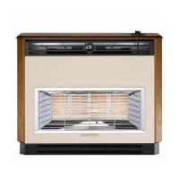
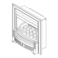
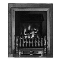
The document describes the Baxi Bermuda Inset 3 Range of Fireside Gas Central Heating Units, which are combined gas-fired central heating boiler and gas fire units designed for installation in a living room. These appliances are intended for use with Natural Gas only and are specifically designed to be used with the Baxi Bermuda Inset 2 Boiler 50/4.
Function Description:
The Baxi Bermuda Inset 3 Range units serve a dual purpose: providing central heating through a boiler and offering a visible gas fire for ambient heat and aesthetic appeal in a living room. The fire unit is controlled by a knob with three positions: OFF, IGNITION/PILOT/LOW, and HIGH OUTPUT, allowing for variable heat settings between LOW and HIGH. The appliance incorporates a flame failure device and an atmospheric sensing device for safety.
Important Technical Specifications:
The fire units are set for Gas Type G20 at 20mbar.
- Heat Input:
- High: 6.52 kW (22,246 Btu/h)
- Low: 4.1 kW (13,989 Btu/h)
- Setting Pressure (Cold): 9.0 mbar (3.6 in wg)
- Thermocouple Output: 6.5 - 10.0 mV
- Gas Connection: Supplied from the service cock on the boiler unit.
- Gas Rate (after 10 mins): 0.60 m³/h (21.0 ft³/h)
- Installation Lifting Weight: 8.5 kg (18.7 lbs)
- Outercase Dimensions:
- Height: 610 mm
- Width: 593 mm
- Depth: 103 mm (from the wall)
Site Requirements:
- Fireplace Opening:
- Height: 560 mm (22 in) min to 590 mm (23 15/64 in) max
- Width: 460 mm (18 in) min to 560 mm (22 in) max
- The wall or surround behind the fire must be non-combustible.
- Non-Combustible Area:
- Height: 625 mm (24 19/32 in)
- Width: 625 mm (24 19/32 in)
- Hearth Mounting:
- Must be of non-combustible material, at least 13 mm (1/2 in) thick.
- Dimensions: 300 mm (12 in) deep by 600 mm (23 5/8 in) wide, fitted centrally.
- Top surface of hearth: Minimum 50 mm (2 in) above floor level, level with the base of the builders opening.
- Cannot be fitted directly onto a combustible floor or carpet.
- A fender rail or upstanding edge of 50 mm (2 in) height can be fitted to the periphery of the hearth.
- Ventilation:
- Permanent ventilation area: 80.1 cm² (12.42 in²).
- Vent can be directly into the room or an adjoining room (not bedroom, toilet, bathroom, or kitchen) with an interconnecting vent.
- Vent must not be installed inside the builders opening.
Usage Features:
- Control: The fire is controlled by a knob located behind a controls access door on the fender assembly. It offers OFF, IGNITION/PILOT/LOW, and HIGH OUTPUT settings, with variable adjustment between LOW and HIGH.
- Coals Arrangement: Specific instructions are provided for arranging the refractory ceramic fibre (R.C.F.) coals to achieve the desired flame picture. It is crucial to use all supplied coals and avoid adding extra ones.
- Safety Information (R.C.F. Coals): The product contains Refractory Ceramic Fibres (R.C.F.). Users are advised to handle these articles carefully to minimize dust/fibre release, wear gloves, and follow normal hygiene rules (no smoking, eating, or drinking in the work area, wash hands). Replaced items should be sealed in heavy-duty polythene bags and labelled as "R.C.F. waste" for disposal.
Maintenance Features:
- Annual Servicing: The fire and boiler should be serviced annually for safety and economy.
- Preparation for Servicing: Involves isolating gas and electricity supplies, removing the controls access door, turning off the gas supply at the service cock, carefully removing all coals, lifting the fender assembly, disconnecting the gas supply pipe, and removing screws retaining the fire combustion box.
- Removal of Controls: Involves unscrewing the gas tap bracket and controls assembly from the combustion box.
- Cleaning the Burner & Injectors:
- Remove the burner from the controls mounting plate and disengage it from the injector.
- Clean the burner with a soft brush, ensuring ports are clear.
- Remove and clean the injector; do not use hard tools.
- Cleaning the Pilot/A.S.D. Assembly:
- No hard tools (pins or wire) should be used.
- The A.S.D. must not be altered or bypassed.
- Ensure the pilot burner aeration hole is free from lint/debris.
- Clean the electrode and target; check spark gap (2.5 - 4.0 mm).
- The thermocouple is not an individual component and requires replacement of the complete assembly if faulty. Only Genuine Baxi Spare Parts should be used.
- Cleaning the Combustion Box & Coals:
- Remove deposits from the firebed base panel.
- Coals can be cleaned with a very soft brush and retouched with black stain.
- Replacing the Fire: After boiler servicing, the fire is reinstalled by sliding the combustion box into position, connecting the flue spigot, fitting retaining screws, reconnecting the gas supply (and testing for soundness), and replacing coals and fender.
- Changing Components: Detailed instructions are provided for replacing the burner, injector, pilot/A.S.D. assembly, gas tap, igniter unit, and electro-magnetic unit. After any component change, gas soundness checks must be performed.
- Spillage Checking: A procedure is outlined to check for spillage, involving operating the fire on maximum (and boiler if applicable) and using a lighted smoke match to verify proper flue draw. This must be done under "worst likely operating environment" conditions (closed doors/windows, operating extractor fans). Possible causes of spillage (incorrect smoke match positioning, unsound flue, inadequate ventilation, downdraughts, flue blockages) are listed.
General Safety and Installation Notes:
- Installation must be carried out by a CORGI Registered Installer or other competent person in accordance with relevant regulations (Gas Safety, Building Regulations, I.E.E. Wiring Regulations, Local Water Undertaking bye-laws, and British Standard Codes of Practice).
- The instructions must be left with the user.
- Users should be shown how to operate the fire and boiler safely and efficiently.
- The importance of annual servicing and returning the guarantee card is emphasized.
- Discolouration of wall surfaces adjacent to heating appliances is a possibility due to warm air convection currents, especially with certain soft furnishings or in environments with high levels of cigarette smoke or contaminants.

 Need help?
 General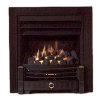


 To Next Page