ProLoop2 11-pin
Supply voltage /
Current consumption /
Power consumption
• 24ACDC: 24 VAC –20 % to +10 %, 84 mA, max. 1.8 VA
24 VDC –10 % to +20 %, 84 mA, 1.3 W
• 230 AC: 230 VAC –15 % to +10 %, 16 mA, max. 3.7 VA
Loop inductance
max. 20 to 1000 µH,
ideally 80
to 300 µH
Loop connection wiring
At 20-40 µH: max. 100 m at 1.5 mm
2
At >40 µH: max. 200 m with 1.5 mm
2
min. twisted 20x/m
Loop resistance
< 8 Ohm with connection wire
Output relay (loop)
AC-1: max. 240 VAC; 2 A / DC-1: max. 30 VDC; 1 A
Dimensions
36 x 74 x 88 mm (W x H x D)
Housing mounting
Mounting rail installation via 11-pin base ES 12
Connection type
Screw terminals base ES 12
Protection class
IP 20
Operating temperature
–20°C to +60°C
Storage temperature
–40°C to +70°C
Air humidity
<95% non-condensing
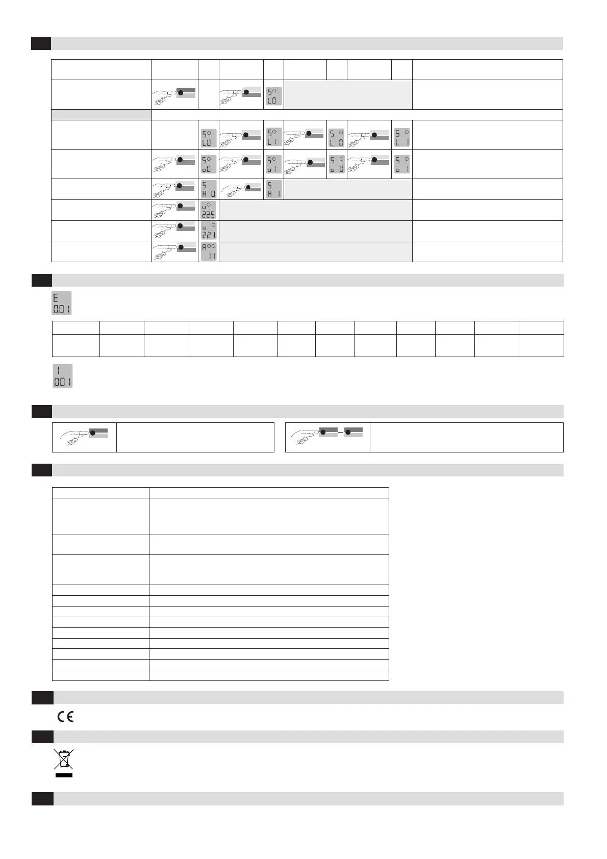
Changeover to simulations mode
Press «Sim1»
button
Press «Sim2»
button
Press «Sim2»
button
Press «Sim2»
button
Anmerkungen
Changeover to simulation mode:
Press the Sim1 + Sim2 buttons
simultaneously for 2 seconds.
1
Simulation mode:
Activation of the loop
1
1
2
2
L0 -No loop activation (time functions are active)
L1 -Loop activation (time functions are active)
- Loop 1 - Loop 2
Activation of the output relay
1
1
2
2
00 - Activation of output
01 - Activation of output
- Loop 1 - Loop 2
Alarm output activation
Data
Sim2
A0 -Switch off alarm relay
A1 -Switch on alarm relay
Inductance of loop 1
1
Measurement of the inductance, value in µH
Inductance of loop 2
2
Measurement of the inductance, value in µH
Exiting simulation mode
1
2
Return to function mode
5
Simulation mode
If an error occurs, operating mode «A» and error display «E» light up alternately and an error code such as E 012 is displayed. The LED changes to
flashing red, the 4 most recent errors are stored and can be interrogated.
Display E001 E002 E011 E012 E101 E102 E201/E202 E301 E302 E311 E312
Error
Interruption
Loop 1
Interruption
Loop 2
Short circuit
Loop 1
Short circuit
Loop 2
Under -
voltage
Over-
voltage
Saving
error
Loop 1
too large
Loop 2
too large
Loop 1
too small
Loop 2
too small
Briefly pressing the «Data» button shows the last of 4 errors on the display. Another short press switches to the error before that, and so on. When
the button is pressed for the 5th time, the device switches back to automatic mode. If you press the «Data» button for 4 seconds during the query,
all error messages are deleted. The figure shows memory slot 1 in which error 001, Interruption loop 1, has been stored (example).
6
Troubleshooting
7
Reset
Mode
Sim1
2 Sekunden
Reset 1 (recalibration)
The loop(s) is/are recalibrated.
Mode
Sim1
8 Sekunden
Data
Sim2
Reset 2 (factory setting)
All values (except the error memory) are reset to the factory
settings (see Table 4.11a). The loop(s) is/are recalibrated.
8
Most important technical data
EU Declaration of Conformity
9
WEEE
10
Devices with this symbol must be treated separately during disposal. This must be done in accordance with the laws of the respective countries
for environmentally sound disposal, processing and recycling of electrical and electronic equipment.
See attachment
4
Contact
11
BBC Bircher Smart Access, BBC Bircher AG, Wiesengasse 20, CH-8222 Beringen, www.bircher.com
Designed in Switzerland / Made in EU
 Loading...