2
NC 2x
C B S
8K2
C B S
8K2
NC
1
+
2032
2
+
+
2032
2032
1 2
ON
8K2 8K2
1 2
ON
IN1
comon
IN2
2)
IN1
comon
IN2
2)
IN2
2)
IN2
2)
1)
1 2
ON
IN1
1 2
ON
IN1
1)
C B S
VCC1
VCC2
COM
OUT
SOUT
TEST
+/~ –/~
12/24V
AC/DC Test
C B S
VCC1
VCC2
COM
OUT
SOUT
TEST
+/~ –/~
12/24V
AC/DC
Test
open
collector
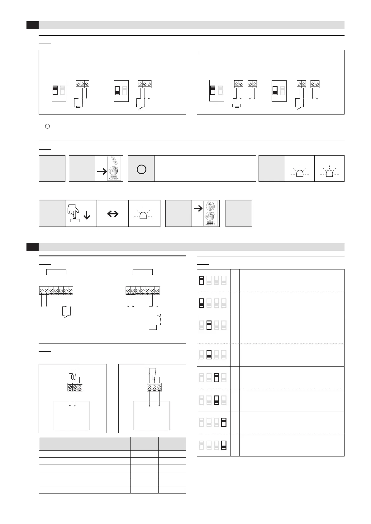
3.2 Change input from NC to NO (factory setting = NC)
4.3 DIP switches
4 Receiver
3 Transmitter
2.
Insert
battery 1
5.
Insert
battery 2
3.
Status
4.
Change
6.
Change
stored
Press button on
transmitter
Status
changes
LED
ashes
LED
ashes 2x
LED
ashes 5x
> 1.5 sec.
After inserting the battery 1,
you have 10 seconds to change the logic
1 2 3 4
ON
*
Safety application
standard
according to EN ISO 13849-1
1 2 3 4
ON
inactive ➔ no safety function!
(Radio connection is not monitored)
1 2 3 4
ON
Transmission frequency
869.85 MHz:
Set DIP-switch before pairing transmitter –
receiver
1 2 3 4
ON
*
868.95 MHz:
Set DIP-switch before pairing transmitter –
receiver
1 2 3 4
ON
Test input type
NC
activated = contact open
1 2 3 4
ON
*
NO
activated = contact closed
1 2 3 4
ON
Automatic frequency adjustment
active
used only in case of radio disturbances
1 2 3 4
ON
*
inactive
* = factory setting
Observe
the sequence
Relay contacts are shown unpowered
4.2 Wiring: Outputs and control
Gate control
with
NC input
Gate control
8.2 kOhm
input
4.1 Wiring: Power supply and test inputs
1)
Change from NC to NO, see chapter 3.2
2)
IN2 has no function
RFGate 2.2.S RFGate 2.2.S.F
3.1 DIP switch setting according to sensor (safety edge, switch contact)
NO 5x
NO
DIP switch Sensor connection DIP switch Sensor connection DIP switch Sensor connection DIP switch Sensor connection
Status Terminals
C – B
Terminals
C – S
Sensor not activated (operating mode) 8K2 closed
Sensor activated (security system activated) closed open
No supply voltage closed open
Transmitter and receiver not paired closed open
Broken cable between sensor and transmitter closed open
Transmitter batteries low closed open
1.
Remove all
batteries
 Loading...