75.5886.01 BR2-900 20170630 Page 3 of 875.5886.01 BR2-900 20170630 Page 3 of 8
USER INTERFACE
DIP switches can be set to achieve desired functionality based upon specific application requirements.
Potentiometers control output relay functionality.
900 MHz wireless transmitters can be programmed (or "learned") as either UNSECURE or SECURE transmitters.
Any combination of up to 75 transmitters may be programmed.
Pressing and holding transmitter button for three (3) seconds activates signal strength LED on Br2-900.
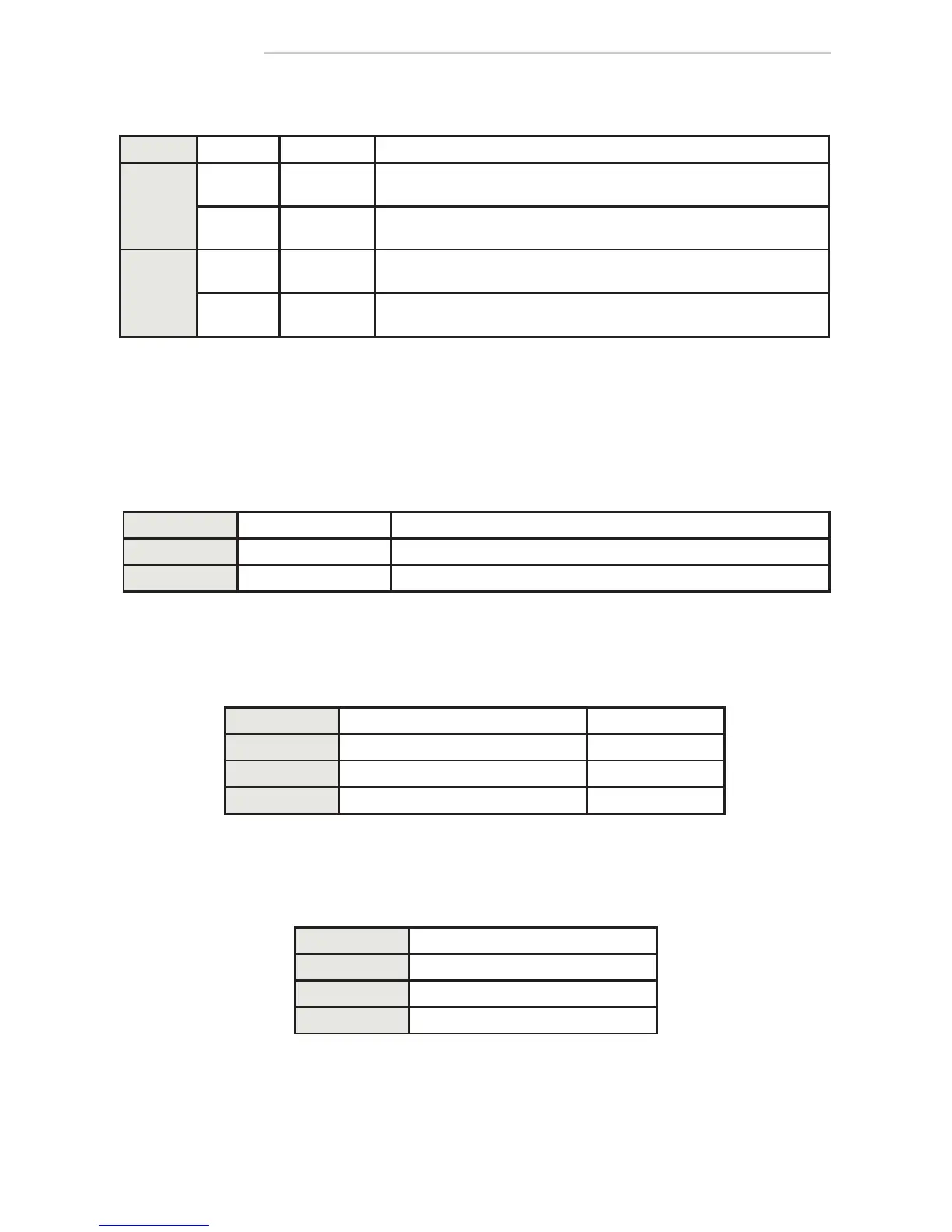
DIP-Switches
DIP STATUS FUNCTION DESCRIPTION
1
STD
standard
mode
allows only learned/programmed transmitters to function
UNI
1
universal
mode
2
allows learned/programmed and "universal transmitters" to function
2
STD
standard
mode
pressing/holding or pressing/releasing transmitter activates and holds
relay according to HOLD TIME POTs (single shot)
EH
extended
hold
pressing/holding transmitter holds relay as long as transmitter is pressed/
held – once released, relay acts according to HOLD TIME POTs
NOTES:
1. Day/Night mode does not function when DIP-switch 1 is set to UNI.
2. See Universal Mode in SET-UP section (page 5).
Potentiometers
Learn Buttons
BUTTON FUNCTION DESCRIPTION
UNSECURE unsecure transmitters learned transmitter functions when INPUT D/N is open or closed
SECURE secure transmitters learned transmitter only functions when INPUT D/N is open
POT FUNCTION DESCRIPTION
HOLD 1 relay 1 hold time 0.5 – 10 seconds
HOLD 2 relay 2 hold time 0.5 – 10 seconds
DELAY delay between relay 1 and relay 2 0 – 3 seconds
Signal Strength Indicator
LED COLOR DESCRIPTION
GREEN strong wireless signal
YELLOW moderate wireless signal
RED weak wireless signal