Do you have a question about the BEA LZR-I100 and is the answer not in the manual?
Essential practices for proper installation and ongoing upkeep to ensure optimal performance and longevity.
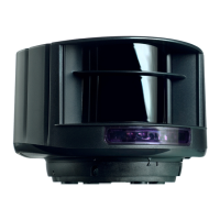
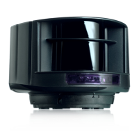
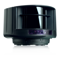
Identifies key physical components of the laser scanner device.
Explains the meaning of various LED colors and flashing patterns for status indication.
Deciphers important symbols related to laser safety, remote control, and factory settings.
Adjusts the number and layout of active detection curtains for safety fields.
Configures the detection zone to compensate for environmental factors like leaves or snow.
Modifies the sensor's sensitivity to environmental interference for stable operation.
Defines the smallest object the sensor will reliably detect.
Sets the behavior of the output relays for different detection events.
Configures how detection signals are redirected or interpreted by the output relays.
Establishes a second detection field to enhance safety during door opening.
Configures virtual push button zones for manual door activation.
Details how to adjust sensor parameters using the remote control.
Explains how to check current sensor parameter values or field configurations.
Guides on restoring the sensor to its original factory default settings.
Covers saving, deleting, and managing access codes for secure remote control access.
Addresses problems related to the absence of the blue power-on LED.
Solves issues where only the blue LED is active, indicating potential power supply problems.
Resolves cases where the detection LED remains green, suggesting test input issues.
Covers scenarios where the detection LED stays red due to small objects or field obstructions.
Diagnoses problems indicated by a flashing orange LED and red detection LEDs.
Addresses issues indicated by a solid orange LED, such as sensor masking or power voltage problems.
Guides on troubleshooting when the sensor does not respond to the remote control commands.
Provides solutions for when the sensor fails to unlock, often due to access codes or reflections.
| Type | Laser scanner |
|---|---|
| Scanning Technology | Laser |
| Operating Temperature | -30°C to +60°C |
| Protection Rating | IP65 |
| Technology | Time-of-Flight |
| Detection Zones | Configurable |
| Supply Voltage | 12-24 V DC |
| Power Supply | 12-24 V DC |
| Output Type | Relay |
| Max. Contact Voltage | 42 V AC/DC |
| Hold Time | Configurable |