75.5366.07 UL MAGLOCKS 20171130 Page 3 of 475.5366.07 UL MAGLOCKS 20171130 Page 3 of 4
Page 2 of 2 75.5366.02 20140401
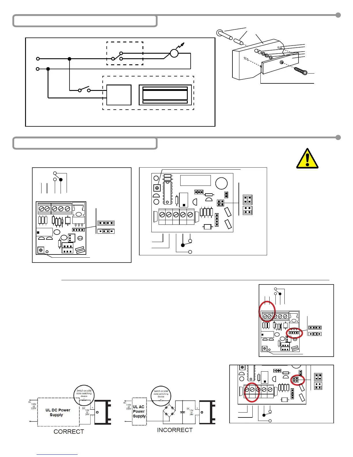
5 Installation - Mechanical & Electrical
LOCK STATUS SWITCH (SPDT)
POWER
SUPPLY
+ -
POWER
SELECTOR
JUMPER
LED
MAG BOND SENSOR
MAGNET
TIMER (0-90 SEC)
TYPICAL INSTALLATION
NOTE: DO NOT over-tighten the armature plate. The rubber washer is designed to allow the armature
plate to automatically adjust position for best mating position between the lock and armature plate.
DOOR FRAME
ARMATURE PLATE
MAGNET
ANGLE
BRACKET
MOUNTING
PLATE
MOUNTING
PLATE
STRINGER
HOLE FOR
GUIDE PIN
HOLE FOR NUT
RUBBER WASHER
STEEL WASHER
ARMATURE PLATE
SCREW M8 (35MM)
GUIDE PIN
DOOR
NUT
SPACER
WASHER
ARMATURE
PLATE
DOOR
NUT
DOOR FRAME
DOOR FRAME
DOOR
ARMATURE PLATE
ARMATURE PLATE
MAGNET
MAGNET
DOOR DOOR
MOUNTING
PLATE
CAUTION: Observe proper
circuit board orientation!
NOTE: The product must be powered from a UL listed, regulated, power limited, power supply.
NOTE: If power switch is not wired between DC source voltage and magnet,
it will take a longer time to de-energize the magnet simulating residual magnetism.
1. 12 VDC INPUT
A. Required power 0.5A (Max).
B. Connect ground (-) lead from a 12 VDC power source to Terminal 2.
C. Connect positive (+) lead from a 12 VDC power source to Terminal 1.
D. Check jumper for 12 VDC operation.
2. 24 VDC INPUT
A. Required power 0.25A (Max).
B. Connect ground (-) lead from a 24 VDC power source to Terminal 2.
C. Connect positive (+) lead from a 24 VDC power source to Terminal 1.
D. Check jumper for 24 VDC operation.
3. CONTACTS
1. Relay dry contacts are rated 1A at 24 VDC for safe operation, DO NOT exceed this
rating.
2. If a NO switch is required, connect the wires from the system to Terminal 4 & Terminal 3.
3. If a NC switch is required, connect the wires from the system to Terminal 4 & Terminal 5.
DS VERSION
24/7 Tech Support: 1-800-407-4545 | Customer Service: 1-800-523-2462 | General Tech Questions: Tech_Services@beainc.com | Tech Docs: www.beasensors.com
Carte de circuit pour les verrous magnétiques 600 lb
REMARQUE : Caractéristiques des bornes : Calibre 12~24 AWG
Carte de circuit pour les verrous magnétiques 1 200 lb
7 Installation – électrique
ATTENTION :
Observez la bonne
orientation de la carte
de circuit!
+ -
G
1 2 3 4 5
+ - NO F NF
12VCC
24VCC
CAVALIER DU
SÉLECTEUR
D’ALIMENTATION
MINUTERIE DU DOUBLE
VERROUILLAGE 0 à 90 S
ALIMEN-
TATION
+ -
RELAIS DE L’ÉTAT DE VERROUILLAGE
G
R B G
R
G
B
W
1 2 3 4 5
+ - NO C NC
12VCC
24 VCC
CAVALIER DU
SÉLECTEUR
D’ALIMENTATION
MINUTERIE DU
DOUBLE
VERROUILLAGE
0 à 90 S
ALIMEN-
TATION
RELAIS DE L’ÉTAT DE VERROUILLAGE
Alignez la pièce en plastique noir de la
plaque d’armature avec la plaque de
protection (c.-à-d., l’aimant doit être
aligné avec le commutateur).
6 Installation de la plaque d'armature
1
PCB
2
sw
+
-
NC
COM
ON
NO
1
PCB
2
VERROU MAGNÉTIQUE
NC
ROUGE
VERT
NOIR
VOYANT
COM
COMMUTATEUR À LAMES
ON
NO
*Le commutateur change l’état lorsque la porte est ouverte
COMMUTATEUR DU CAPTEUR D’ÉTAT DE PORTE*
Trou pour broche guide
Trou pour écrou
Rondelle en caoutchouc
Rondelle en acier
Plaque d’armature
Écrou
Accessoire d’espacement
Porte
Vis M8 35mm
Broche guide
Le produit doit être mis sous tension à l’aide d’une alimentation électrique homologuée
UL, régulée et limitée en puissance!
Si l’interrupteur n’est pas câblé entre la tension source CC (+) et l’aimant, le temps pour
mettre hors tension l’aimant simulant un magnétisme résiduel sera plus long.
ENTRÉE 12 V CC
- Alimentation requise Consultez les spécications à la page 2.
- Connectez le l positif (+) à partir d’une source d’alimentation 12 V CC à la borne 1.
- Connectez le l négatif (-) à partir d’une source d’alimentation 12 V CC à la borne 2.
- Vériez le cavalier pour le fonctionnement en 12 V CC.
ENTRÉE 24 V CC
- Alimentation requise : Consultez les spécications à la page 2.
- Connectez le l positif (+) à partir d’une source d’alimentation 24 V CC à la borne 1.
- Connectez le l négatif (-) à partir d’une source d’alimentation 24 V CC à la borne 2.
- Vériez le cavalier pour le fonctionnement en 24 V CC.
(600 lb)
(1 200 lb)
G
R B G
R
G
B
W
1 2 3 4 5
+ - NO C NC
12VCC
24 VCC
CAVALIER DU
SÉLECTEUR
D’ALIMENTATION
MINUTERIE DU
DOUBLE
VERROUILLAGE
0 à 90 S
ALIMEN
-
RELAIS DE L’ÉTAT DE VERROUILLAGE
+ -
G
1 2 3 4 5
+ - NO F NF
12VCC
24VCC
CAVALIER DU
SÉLECTEUR
D’ALIMENTATION
MINUTERIE DU DOUBLE
VERROUILLAGE 0 à 90 S
ALIMEN-
TATION
+ -
RELAIS DE L’ÉTAT DE VERROUILLAGE
ALIMENTATION
 Loading...