Group 22
Quick Reference
11
COUPLING
THUMB NUT
SWITCH CAMS
COUNTER-CLOCKWISE SWITCH
CLOCKWISE SWITCH
PIN CONNECTORS
AUXILIARY
SWITCH S2
AUXILIARY
SWITCH S1
THUMB NUT
LOCKING SCREW
(Do Not Adjust Set Screws (4))
CONTACTLESS POSITION SENSOR
(CPS-4)
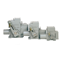
CONTROL END / CONTACTLESS POSITION SENSOR
CONTROL END
The control end assembly is comprised of
the contactless position sensor (CPS-4), limit
switches, and limit switch cams. The control end
assembly is located in the actuator’s control end
compartment under the cylinder shaped cover.
The assembly is installed on the control shaft
which is geared into the main output shaft of
the actuator. As the output shaft turns it moves
the control shaft , the limit switch cams, and the
contactless position sensor ferrite core.
The control end includes two SPDT auxiliary
limit switches (labeled S1 and S2) for customer
connection and two over-travel limit switches
(labeled CW and CCW). The cams can be adjusted
to actuate the auxiliary switches anywhere in the
actuator’s range of travel.
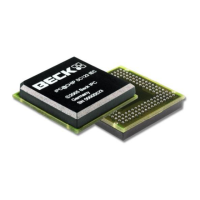
CONTACTLESS POSITION SENSOR
(CPS-4)
The contactless position sensor (CPS-4) is a
circuit board and sensor assembly that is part of
the control end assembly. The CPS-4 provides
the DCM-2 with a continuous position signal
proportional to the position of the actuator’s output
shaft. The CPS-4 is located in the actuator’s
control end compartment under the cylinder
shaped cover.
The position sensing function of the CPS-4 is
provided by a ferrite magnetic sensing element.
An electronic circuit translates the voltage from
the ferrite magnetic sensor into a position signal.
The position signal is used by the DCM-2 to
determine the actuator’s output shaft position for
control and to generate an analog 4-20 milliamp
position feedback signal for external use.
LOCAL PUSHBUTTON INTERFACE
The five pushbuttons located on the local
pushbutton interface are used for simple calibration
features. To utilize the pushbuttons, the user must
press and hold the calibrate button, then press and
hold the button for the desired function. Pressure
should be maintained until the “ACKNOWLEDGE”
LED lights; this confirms receipt of the pushbutton
command.
See the calibration section of this manual for
further explanation of the calibration procedures.
CAUTION
Pressing the following buttons may
change calibration and cause the drive to
reposition.
CALIBRATE
As a safety feature, this button must be
pressed and held simultaneously with another
pushbutton to perform a calibration.
SET POS 100%
Calibrates the DCM-2 to recognize the current
output shaft position as the 100% position.
SET POS 0%
Calibrates the DCM-2 to recognize the current
output shaft position as the 0% position.
SET DEM 100%
Calibrates the DCM-2 to recognize the
currently applied demand signal as the 100%
demand signal.
SET DEM 0%
Calibrates the DCM-2 to recognize the
currently applied demand signal as the 0%
demand signal.
 Loading...