Group 22
Quick Reference
3
SUPPLY POWER
TERMINALS 1, 2, AND 3
Standard supply power for the model 22-309 is
single-phase 120 VAC (refer to the drive nameplate
for specific rating). Input power connects line to
terminal 1, neutral to terminal 2, and ground to
the enclosure power ground screw. Terminal 3 is
unused for 120 VAC operation.
Standard supply power for the model 22-409
is three-phase 208 VAC. Standard supply power
for the model 22-809 is three-phase 480 VAC.
Lines 1, 2, and 3 connect to terminals 1, 2, and 3
respectively on each of these drives. The ground
wire should be connected to the enclosure power
ground screw.
Alternate voltage options include single-phase
240 VAC for the model 22-309 and three-phase
208, 240, 380, 416, 480, & 575 VAC for all Group
22 models. The model 22-309 and 22-409 require
an optional transformer enclosure to accommodate
any non-standard voltage configuration.
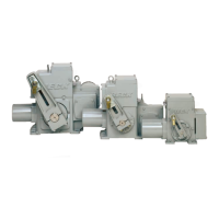
Group 22 drives are equipped with a transient
protector assembly installed across each, or a
combination of terminals 1, 2, and 3 (dependent
upon your drive model and configuration). Note:
The transient protector assembly should not be
removed.
AUXILIARY LIMIT SWITCHES
TERMINALS 4 THROUGH 9
Group 22 drives include two single pole double
throw (SPDT) auxiliary limit switches rated for 1
Amp at 250 VAC. These switches may be useful
for discrete position indication. The limit switches
are actuated by adjustable cams on the control
shaft (located with the position sensing device).
Details on standard factory switch settings can be
found in the configuration section of this manual.
AUTO MODE INDICATION
TERMINALS 10 AND 11
A dry contact is available at terminals 10 and
11 to indicate when the handswitch is in the AUTO
position. The switch contact is Form A; when
the handswitch is not in the AUTO position, the
contact is open and when the handswitch is in the
AUTO position, the contact is closed. The contact
is rated for 1 Amp at 250 VAC.
CAUTION
Always close covers immediately after
installation or service to prevent moisture or
other foreign matter from entering the drive.
SYSTEM ALARM
TERMINALS 12 AND 13
Indication of the system alarm is available as
a dry contact at terminals 12 and 13. The factory
standard is a form B contact configuration (open on
alarm). It is configurable to a form A configuration
(closed on alarm). Reference the configuration
section of the manual for additional details on how
to change this functionality. The contact is rated
for a maximum of 80 milliamps at 120 VAC/VDC.
DEMAND SIGNAL
TERMINALS 14 AND 15
The DCM monitors an analog 4-20 milliamp
input signal at terminals 14 (–) and 15 (+), and
positions the output shaft position to match in
response. The standard response is to follow the
demand signal linearly.
FEEDBACK SIGNAL
TERMINALS 16 AND 17
When feedback sourcing is enabled, the DCM-2
transmits a 4-20 milliamp position feedback signal
on terminals 16 (–) and 17 (+) that is proportional
to the drive output shaft position.
CONTROL OVERRIDE INPUTS
TERMINALS 18 THROUGH 21
Analog signal operation may be overridden by
using discrete input signals on the control override
input terminals. CW (19), CCW (20), and STOP
(21) terminals require connection to a common
(COM) terminal (18) to perform the override as
shown in the table below.
Terminal
Connections
Output Shaft
Action
19 to 18 Clockwise Rotation
20 to 18 Counter-Clockwise Rotation
21 to 18 Stop in Current Position
The connection to terminal 18 is designed to
be made through relay contacts or through a solid
state switch capable of sinking at least 5 milliamps
DC. When the circuit is open, terminals 19, 20,
and 21 should measure +12 VDC with respect to
terminal 18.
CAUTION
Do not connect an external voltage source to
override terminals 18–21; an external voltage
source may damage the DCM circuitry.
 Loading...