Subject to correction and technical modifications 30 Copyright by Becker GmbH, D-76303 Karlsbad
,QVWDOODWLRQJXLGH
0HFKDQLFDOVSHHGRPHWHUZLWKLQWHJUDWHGVSHHGVHQVRULQWKHVSHHGRPHWHUFDEOH
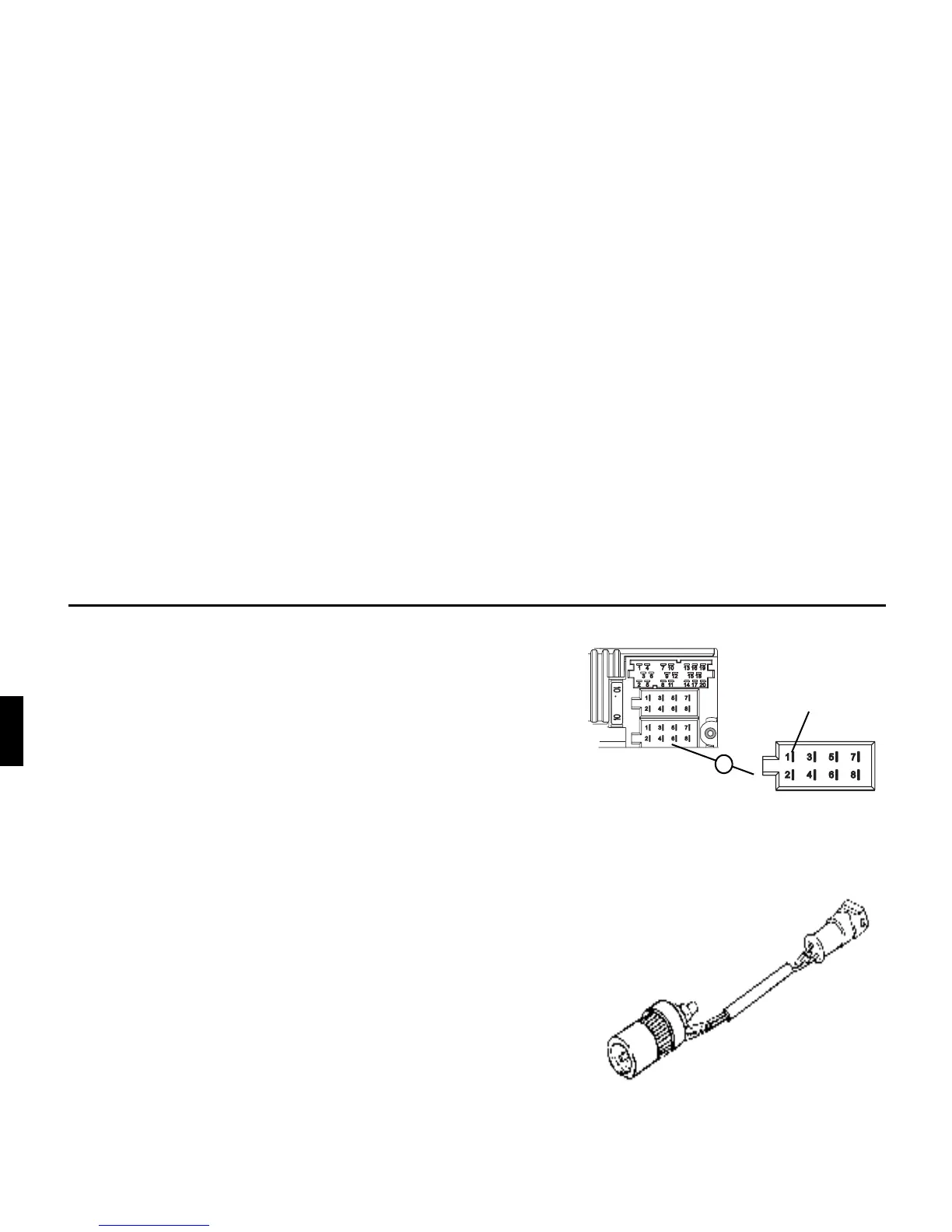
• Remove the signal from the speed sensor, extend and connect to
socket A pin 1.
• Minimum requirement for the signal:
+]N+]VTXDUHZDYHVLJQDOQRLQGXFWLYHVHQVRU
/RZOHYHO9KLJKOHYHO99
)
If you do not know the exact installation position / location
of the speed signal, please consult the vehicle manufactur-
er.
0HFKDQLFDOVSHHGRPHWHUZLWKRXWVSHHGVHQVRULQWKHVSHHGRPHWHUFDEOH
A speed sensor which generates a digital, speed-dependent signal must
be installed in the speedometer cable.
The VDO adapter 2152.30300000 or a vehicle-specific adapter which
satisfies the minimum requirements can be used. The VDO speed sen-
sor is suitable for direct installation on the gearbox (no further installa-
tion parts required) or in the speedometer cable (in conjunction with
additional universal installation parts).
)
If the sealed speedometer cable is released, a correct dis-
play cannot be guaranteed. Incorrect installation leads to
improper functioning of the navigation system or of the
speedometer.
*$/VLJQDO
$