Subject to correction and technical modifications 31 Copyright by Becker GmbH, D-76303 Karlsbad
,QVWDOODWLRQJXLGH
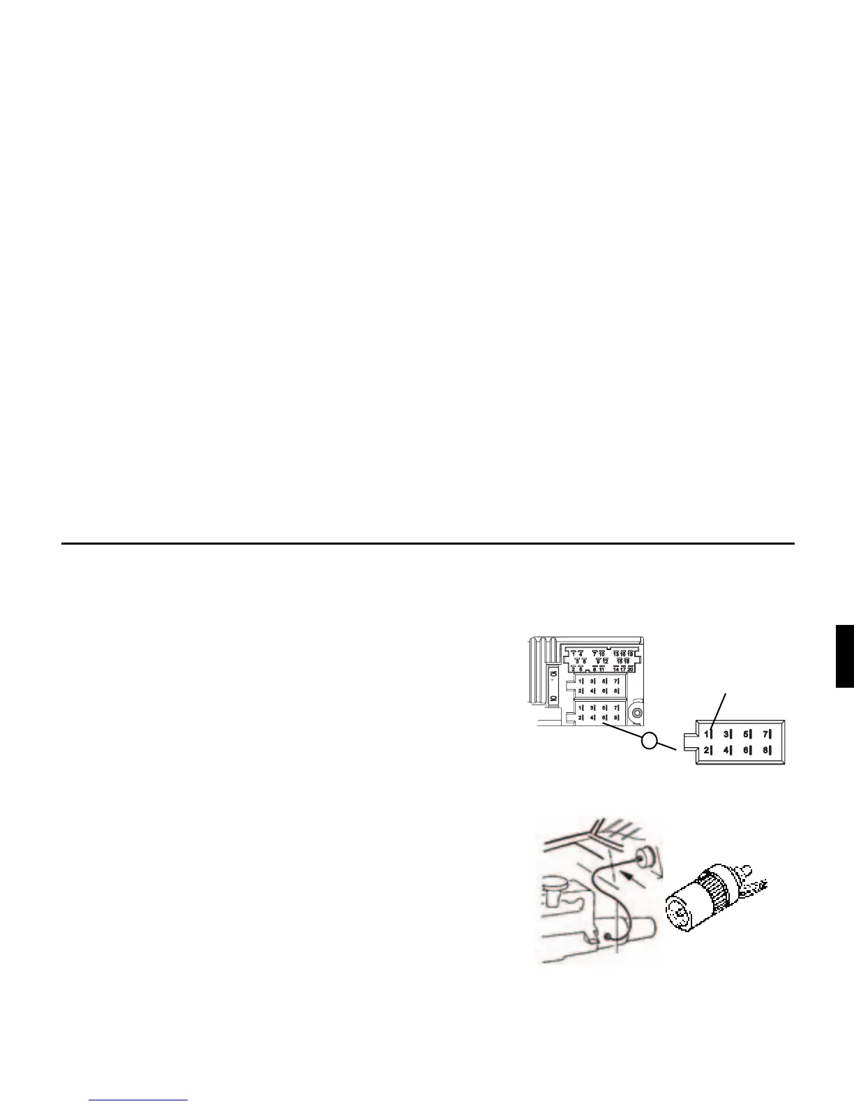
,QVWDOOLQJWKHVSHHGVHQVRUGLUHFWO\RQWKHJHDUER[
• Release the speedometer cable and screw speed sensor onto gear-
box. Screw released speedometer cable onto the speed sensor and
connect the wires.
:LUHFRQQHFWLRQVIRUWKHVSHHGVHQVRU
Brown - earth (terminal 31)
Black - power supply (terminal 15), 9 - 16V, 30 mA
Blue/red - signal for socket A pin 1
,QVWDOOLQJWKHVSHHGVHQVRULQWKHVSHHGRPHWHUFDEOH
In order to install the speed sensor, the speedometer drive cable must be
cut in one even piece for insertion of the speed sensor. When removing
the speedometer cable from the vehicle, ensure that the location of the
evenly running piece is established and marked accordingly.
Installation is illustrated without reference to any specific vehicle. In
addition to the sensor, the following VDO universal parts are required:
1 x connecting piece 1040 1300 025 (VDO part number)
2 x knurled nuts1 040 1000 003 (VDO part number)
2 x hose sleeves 1040 1000 031 (VDO part number)
2 x dogs 1 040 1000 049 (VDO part number)
2 x friction washers 1040 0900 003 300 (VDO part number)
2 x fuel washers 4.0 KN07.0570.18 (VDO part number)
2 x washers KN11.1904.122 (VDO part number)
An appropriate, complete kit from VDO (part number X 39397106191)
can also be used.
*$/VLJQDO
$
)LJXUH