Parameterization and commissioning
BK9053, BK910324 Version: 2.3.0
4 Parameterization and commissioning
4.1 Start-up behaviour of the Bus Coupler
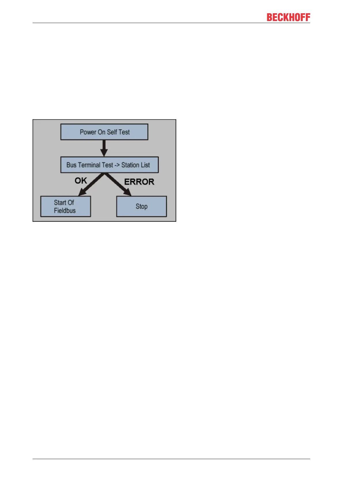
Immediately after being switched on, the Bus Coupler checks, in the course of a self-test, all the functions of
its components and the communication on the K-bus/E-bus. The red I/O LED blinks while this is happening.
After completion of the self-test, the Bus Coupler starts to test the attached Bus Terminals (the "Bus
Terminal Test"), and reads in the configuration. The Bus Terminal configuration is used to generate an
internal structure list, which is not accessible from outside. In case of an error, the Bus Coupler enters the
Stop state. Once the start-up has completed without error, the Bus Coupler enters the fieldbus start state.
Fig.10: Start-up behaviour of the Bus Coupler
The Bus Coupler can be made to enter the normal operating state by switching it on again once the fault has
been rectified.