Assembly and connecting
CX9000 / CX9010 35Version: 2.6
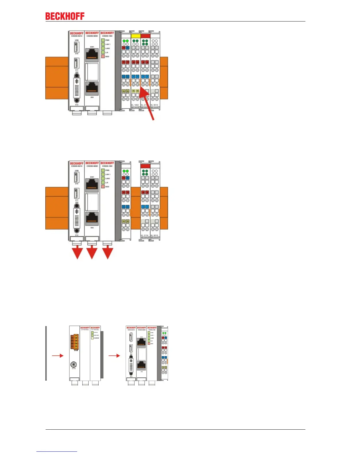
1.2. Releasing the CX90x0 system
In order to release the CX-block, pull the white straps at the bottom of the module in the direction of the
arrows. They will lock in the extended position. After pulling the terminal release of the power supply unit, the
block can be removed carefully from the top-hat rail.
2 Assembly of the CPU basic module with UPS module
2.1 Assembly the the CX90x0 system block
In order to be able to connect the UPS to the basic CX90x0 module, the cover of the basic module has to be
removed first. This is achieved by applying slight pressure on the cover. The individual modules are simply
plugged together. The PC104 connector plugs should be handled carefully in order to avoid damage. When
correctly assembled, no significant gap can be seen between the attached housings. If the modules are
assembled the cover can be replaced.
2.2 Engaging on the top-hat rail
Before engaging the system back on the top-hat rail the user should ensure all white tension straps are
pulled down. The user should take care of the space between the terminals and the Embedded PC system.
The space for the removed terminal must be kept to reinstall the terminal.
 Loading...


