Do you have a question about the BECKWITH ELECTRIC M-3425 and is the answer not in the manual?
Overview of the instruction book's structure, chapters, and appendices.
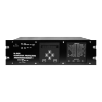
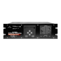
Introduction to the M-3425 relay, its capabilities, and features.
Details on optional modules like HMI and Target Module.
Details on the phase distance protection function (21) with dual-zone mho characteristic.
Information on the Volts/Hz protection function (24) for overexcitation.
Details on the 27TN function for third harmonic neutral undervoltage protection.
Description of the RMS Undervoltage protection function (27).
Explanation of the Directional Power function (32) for generator motoring and overload.
Details on the Loss of Field protection function (40).
Explanation of the Negative Sequence Overcurrent function (46) for unbalanced conditions.
Information on the Breaker Failure protection function (50BF).
Details on the Instantaneous Overcurrent protection function (50).
Explanation of the Instantaneous Neutral Overcurrent function (50N).
Details on the Definite Time Overcurrent function (50DT) for split-phase differential.
Information on the Inadvertent Energizing protection function (50/27).
Explanation of the Inverse Time Neutral Overcurrent function (51N).
Details on the 51V function for phase overcurrent with voltage control/restraint.
Explanation of the RMS Overvoltage protection function (59).
Information on the RMS Overvoltage, Neutral function (59N).
Details on the VT Fuse-Loss Detection function (60FL).
Explanation of the Out of Step protection function (78).
Information on the Frequency protection function (81).
Details on the Rate of Change of Frequency function (81R).
Explanation of the Phase Differential Current function (87).
Information on the Ground Differential function (87GD).
Details on the External Functions (EXT) for external device integration.
Explanation of the 51T function for stator thermal protection.
Details on the Field Ground Protection function (64F).
Specifications for dielectric and impulse voltage withstand tests.
Insulation resistance test requirements according to IEC 255-5.
Requirements for electrostatic discharge and fast transient disturbance tests.
Specifications for surge withstand capability tests per ANSI/IEEE C37.90.1.
Requirements for radiated susceptibility testing per ANSI/IEEE C37.90.2.
Diagram illustrating high-impedance grounding with 3rd harmonic 100% ground fault protection.
Diagram showing low-impedance grounding with overcurrent stator ground fault protection.
Diagram for high-impedance grounding with 3rd harmonic 100% ground fault protection.
Diagram for low-impedance grounding with overcurrent stator ground fault protection.
Tests and standards compliance for the Field Ground Coupler.
Isolation and impulse voltage withstand test specifications for the coupler.
Impulse voltage test parameters per IEC 255-5.
Requirements for ESD and fast transient disturbance tests for the coupler.
Surge withstand capability specifications per ANSI/IEEE C37.90.1.
Radiated susceptibility test requirements per ANSI/IEEE C37.90.2.
Environmental test conditions including temperature and humidity.
Enclosure protection ratings (NEMA 1, IEC IPC-65).
Warning regarding hazardous voltage levels and necessary precautions.
General safety rules and qualifications for personnel handling the equipment.
Instruction to ensure proper grounding of the chassis to prevent shock hazards.
Warning against operating the equipment in flammable or explosive atmospheres.
Precautions regarding working near live circuits and avoiding electrical shock.
Guidance on careful procedures for installation, operation, and maintenance.
Warning against unauthorized modifications and advising return for service.
Caution for handling MOS circuitry and preventing static damage.
Warning against measuring resistances on the circuit board to prevent damage.
Overview of the instruction book's structure, chapters, and appendices.
Introduction to the M-3425 relay, its capabilities, and features.
Details on optional modules like HMI and Target Module.
Description of the relay's front panel controls and indicators.
Step-by-step guide for initial setup and entering relay settings.
Instructions for monitoring relay status, metering quantities, and history.
Information on viewing and clearing the relay's target history.
Overview of remote operation using M-3820A IPScom® software.
Guide for installing and setting up the IPScom® software.
Procedures for activating and operating communication via IPScom®.
Instructions for checking status and metering in Windows environment.
Important warnings and compatibility notes for IPScom® and system setup.
List of keyboard shortcuts for Windows and IPScom® navigation.
Information on the IPSutil™ software for relay setup without HMI.
General information required for relay installation, including diagrams.
Details on physical dimensions and mounting requirements for the relay.
Procedures for checking CT and VT connections during commissioning.
Information on circuit board switches and jumper configurations.
List of required equipment and general setup for testing procedures.
Procedures for performing diagnostic tests on controls, inputs, and outputs.
Details on auto-calibration procedures for the relay and specific functions.
Step-by-step procedures for testing each relay function's operation.
Photocopy-ready forms for recording relay configuration and settings.
Information on communication ports, protocols, and topologies.
List of self-test error codes and their descriptions for troubleshooting.
Graphs of inverse time curve families for various protection functions.
| Frequency | 50/60 Hz |
|---|---|
| Storage Temperature | -40°C to +85°C |
| Humidity | 5% to 95% non-condensing |
| Voltage Rating | 300V |
| Current Rating | 5A or 1A |
| Frequency Range | 50/60 Hz |
| Communication | Modbus |
| Protection Functions | Overcurrent |
| Display | LCD |
| Certifications | UL, CE |