Do you have a question about the BECKWITH ELECTRIC M-3425A and is the answer not in the manual?
Provides a review of manual contents and installation considerations.
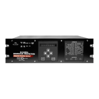
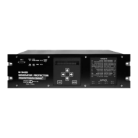
Describes the microprocessor-based unit for generator protection.
Lists optional modules and accessories for the M-3425A relay.
Explains the layout and function of front panel indicators and controls.
Details operation using HMI or IPScom software via serial port.
Provides an overview of IPScom features and functions.
Covers general unit setup, communications, and oscillograph settings.
Defines common information like CT/VT ratios and nominal values.
Provides functional and connection diagrams for typical applications.
Describes enabling functions, setpoints, and I/O assignments.
Provides a review of manual contents and installation considerations.
Contains physical dimensions for mounting the unit on a rack.
Details terminal connections, power supply, and grounding.
Outlines a checkout procedure for external CT and VT connections.
Details access to circuit board switches and jumpers.
Represents typical connections for low frequency signal injection.
Guides on IPScom software installation.
Explains steps for establishing initial local communications.
Provides a suggested procedure for entering relay settings.
Lists equipment and setup procedures for testing.
Details test quantities, inputs, and procedures for each function.
Details diagnostic tests for relay components.
Describes the auto-calibration procedure.
Sets up communication parameters for COM ports and Ethernet.
Configures system parameters like nominal voltage and CT/VT ratios.
Details setpoints for Phase Distance functions.
Describes the relay's RS-232 and RS-485 serial ports.
Details Ethernet port capabilities for network access.
Lists and describes self-test error codes.
Lists and describes IPScom error messages.
Defines operating time calculation based on IEC and ANSI/IEEE.
Provides constants for overcurrent relay time delay settings.
Specifies recommended ambient temperature and humidity for storage.
Recommends periodic power application to prevent capacitor drying.
Details steps to verify system clock status is stopped.
Provides an overview of the HMI menu structure and navigation.
Illustrates the HMI menu flow for various relay functions.
| Frequency | 50/60 Hz |
|---|---|
| Enclosure | Panel Mount |
| Oscillography | Yes |
| Event Recording | Yes |
| Type | Protection Relay |
| Current Rating | 1A or 5A AC |
| Protection Features | Overcurrent, Thermal Overload |
| Communication | Modbus |
| Metering | Voltage, Current, Power, Energy, Frequency |