6. After shifting the sliding frame into its desired position, block it with both the front and
rear locking clamps U bolts (see #2, fig. 5)
6
. Grease driveline cross and bearing
assemblies. Grease sliding sections of shaft.
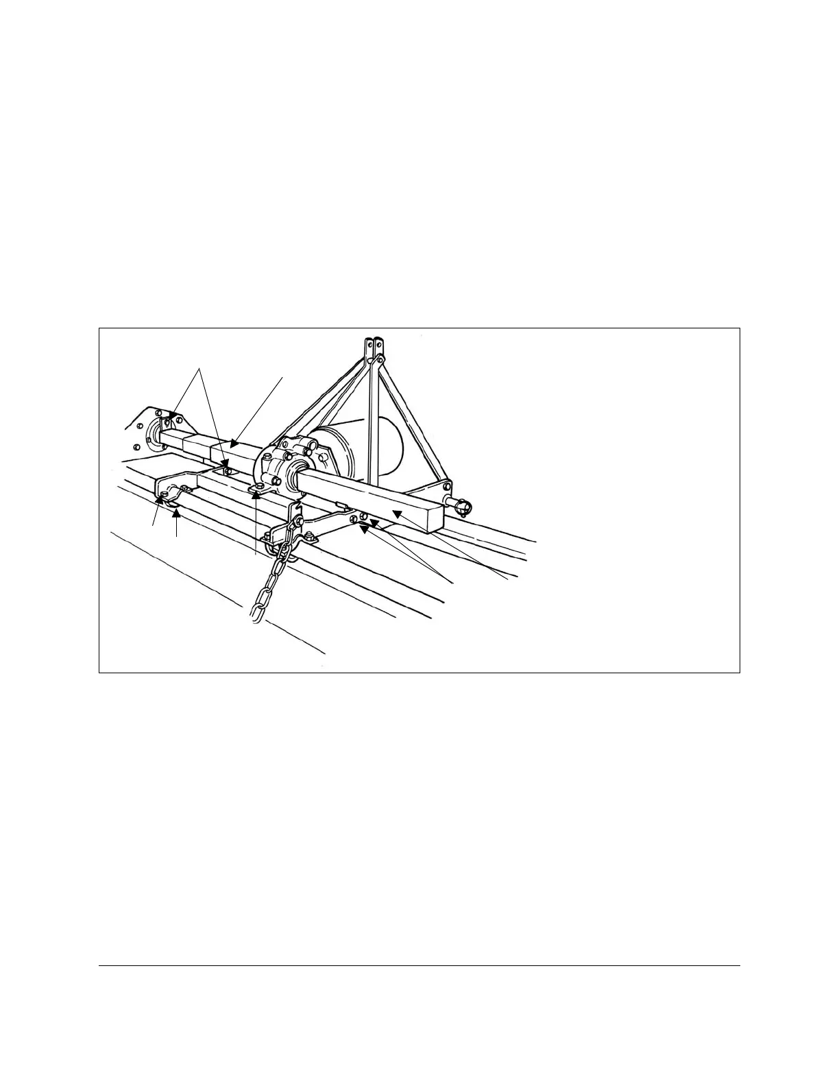
7. The hexagonal drive shaft is protected by a telescopic sliding shield (see #5, fig. 5).
To attach this shield do the following: bolt the upright tab to the chain case side plate
(see #4, fig. 5); open the telescopic shield and bolt the outer cover to the retaining
plate on the sliding frame (see #1, fig. 6); ensure the telescopic shielding when open
does not touch the hexagonal shaft and is parallel as possible; slide the frame back
two or three times from completely open to completely closed to be sure it opens
and closes without difficulty. Note: Lightly greasing the hexagonal drive shaft helps
to side-shift the tiller.
8. Grease right rotor support bearing (see #4 & 5, fig. 3).
9. Hook up the rear shield (see #1, fig. 7) adjustment chain as follows: slip one end of
the chain (see #2, fig. 7) through the ‘U’ bolt (see #3, fig. 7) and then bolt it to the
rear shield in the predisposed holes. Bolt the other end of the chain to the chain
hitch located on the tiller frame (see #4, fig. 7). Ensure it is tightened properly. The
chain hitch also works as a stop for the sliding frame to limit its travel.
OPERATION 14 BEFCO
T
ILL-RITE T50 OPERATOR’S MANUAL
6
See Section 3.03 - Side-Shift.
Fig. 6
1. shield bolts
2. sliding frame support
3. U bolt
4. telescopic shield
5. right shield
6. gearbox holding bolt
1
1
2
3
6
4
5
 Loading...