(11) F CV 1 – Use this jack to route external control voltage or
modulation signals for the lter frequency setting into the
module via cables with 3.5 mm connectors.
(12) F CV 2 – Use this jack to route external control voltage or
modulation signals for the lter frequency setting into the
module via cables with 3.5 mm connectors.
(13) Q CV – Use this jack to route external control voltage
signals for the RESONANCE (Q) setting into the module via
cables with 3.5 mm connectors.
(14) LP – This jack sends out the nal signal from the low-pass
lter via cables with 3.5 mm connectors.
(15) HP – This jack sends out the nal signal from the high-
pass lter via cables with 3.5 mm connectors.
(16) NOTCH – This jack sends out the nal signal from the
notch lter via cables with 3.5 mm connectors.
(17) BP – This jack sends out the nal signal from the band-
pass lter via cables with 3.5 mm connectors.
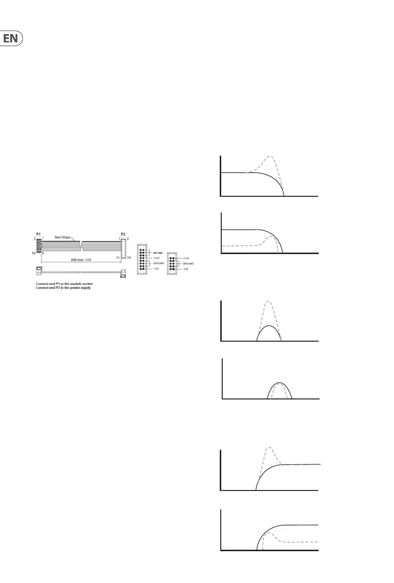
Power Connection
The MULTIMODE FILTER / RESONATOR MODULE 1047 module
comes with the required power cable for connecting to a standard
Eurorack power supply system. Follow these steps to connect
power to the module. It is easier to make these connections before
the module has been mounted into a rack case.
1. Turn the power supply or rack case power o and
disconnect the power cable.
2. Insert the 16-pin connector on the power cable into the
socket on the power supply or rack case. The connector has
a tab that will align with the gap in the socket, so it cannot
be inserted incorrectly. If the power supply does not have
a keyed socket, be sure to orient pin 1 (-12 V) with the red
stripe on the cable.
3. Insert the 10-pin connector into the socket on the back of
the module. The connector has a tab that will align with the
socket for correct orientation.
4. After both ends of the power cable have been securely
attached, you may mount the module in a case and turn on
the power supply.
Installation
The necessary screws are included with the module for mounting in
a Eurorack case. Connect the power cable before mounting.
Depending on the rack case, there may be a series of xed holes
spaced 2 HP apart along the length of the case, or a track that allows
individual threaded plates to slide along the length of the case.
The free-moving threaded plates allow precise positioning of the
module, but each plate should be positioned in the approximate
relation to the mounting holes in your module before attaching
the screws.
Hold the module against the Eurorack rails so that each of the
mounting holes are aligned with a threaded rail or threaded
plate. Attach the screws part way to start, which will allow small
adjustments to the positioning while you get them all aligned. After
the nal position has been established, tighten the screws down.
Filter Curves
Q=2
NORMAL MODE
Q=½
16 KHzFc
16 KHzFc
Q=2
LIMIT MODE
Q=½
16 Hz 16 KHzFc
16 Hz
Fc
Q=2
NORMAL MODE
Q=½
Q=2
LIMIT MODE
Q=½
16 KHzFc
Q=2
NORMAL MODE
Q=½
Q=2
LIMIT MODE Q=½
2 MULTIMODE FILTER / RESONATOR MODULE 1047