Quick Start Guide
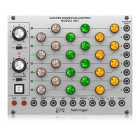
960 SEQUENTIAL
CONTROLLER
Legendary Analog Step Sequencer Module
for Eurorack
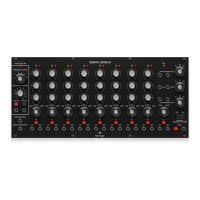
Controls
(1)
(9)
(8)
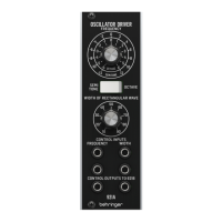
(1) OSCILLATOR - Select the broad oscillator range with the Frequency Range
knob, and ne tune with the Frequency Vernier knob. Engage or disengage
the oscillator manually with the OSC ON and OFF buttons, or connect
external voltage trigger (V-trig) signals to control the on/o status.
(2) CONTROL INPUT - Accepts voltage from another module to control the
oscillator frequency.
(3) OSCILLATOR OUTPUT - Send the oscillator signal via 3.5 mm TS cable.
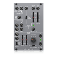
(4) IN - Activate any stage via an external voltage trigger (V-trig). Note that if
a stage IN is patched to another stage OUT, it will cause the 960 to reset to
stage 1, bypassing stages after the OUT jack.
(5) OUT - Send the voltage trigger (V-trig) signal to another module.
(6) SET - Manually activate a stage. In the event of a sequencing error, press
any SET button to reset to a stage and restore normal operation.
(7) STAGE MODE - In the Normal setting, the stage runs its cycle and proceeds
to the next stage. Selecting the Skip setting will bypass the stage, and
selecting Stop will stop the sequence. A 9th stage exists to continue
the sequence (Skip) or Stop the sequence at stage 9 which makes the
stage 9 output active. Whenever stage 9 becomes active, the oscillator is
automatically turned o.
(8) VOLTAGE CONTROLS - Adjust the voltage for each stage. The associated
LED will light to indicate the currently-active stage.
(9) OUTPUT SECTION - Send the voltage from the 8 stages to other modules.
The outputs can be scaled with the associated knobs by a factor of 1, 2 or 4.
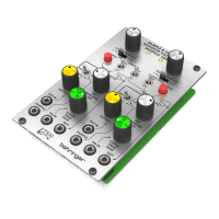
(10) 3RD ROW TIMING - Since many users will run the 960 as an 8-stage or
16-stage sequencer (via the 962 module), the 3rd row can alternatively
be used to control the timing of each stage. Move the switch to the ON
position and adjust each stage’s 3rd knob to lengthen or shorten
the duration.
(11) SHIFT - Control the shifting via an external source or manually with
the button.
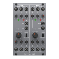
24-Stage Operation
OUT TO
MODULE
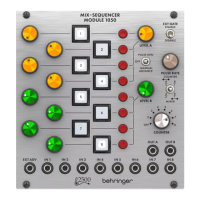
The main purpose of the 962 sequential switch module is to alternately select
between the 3 output rows of the 960 to create a 24-stage sequence. Patch the
trigger OUT jack from stage 1 into the SHIFT input of the 962. Patch the 3 output
rows A, B, C from the 960 to the 962's 3 SIG inputs. Now the 962's output will be
the 24-stage sequencer output, or leave out the C row patch cable for 16 steps.
Tuning Procedure
1. Power up the 960 module and press the OSC ON button. Allow the unit to
warm up for a few minutes.
2. Prepare the following control settings:
a. Set the 3RD ROW CONTROL OF TIMING switch to o.
b. Set the FREQUENCY rotary switch to 6 on the scale.
c. Make sure no jack is connected to the oscillator CONTROL INPUT.
3. Set the FREQUENCY VERNIER for exactly 100 Hz at the OSCILLATOR OUTPUT
measured with an accurate frequency meter and adjust the DUTY CYCLE ADJ
for 90% duty cycle.
4. Fine-tune the 960 oscillator’s high frequency scaling as follows:
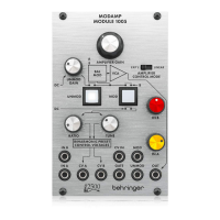
a. Apply exactly +2.0 VDC to the CONTROL INPUT jack (A 921A module
can be used to supply the +2.0 VDC or use a similar low-impedance
stable-voltage source).
b. Trim the 960 SCALE ADJ trimmer to set 400 Hz, then remove the
+2.00 V input and readjust the 960 FREQ VERNIER to 100 Hz.
c. Repeat this cycle until both 100 Hz and 400 Hz are accurate to ±1 Hz
when the +2.00 VDC is plugged in and out of CONTROL INPUT jack.
5. Fine-tune the 960 oscillator’s low frequency scaling as follows:
a. Apply exactly -2.0 VDC to the CONTROL INPUT jack (A 921A module
can be used to supply the -2.00 VDC or use a similar low-impedance
stable-voltage source).
b. Trim the 960 LOW END ADJ trimmer to set 25 Hz, then remove the
-2.00 V input and readjust the 960 FREQ VERNIER to 100 Hz.
c. Repeat this cycle until both 100 Hz and 25 Hz are accurate to ±1 Hz
when the -2.00 VDC is plugged in and out of CONTROL INPUT jack.
V 1.0