Quick Start Guide
961 INTERFACE
Legendary Analog Multi-channel
Trigger Converter Module for Eurorack
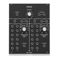
Controls
(1) AUDIO IN – Use this 3.5 mm jack to route an audio
signal into the module for conversion to a V-Trig
(voltage trigger) signal. The audio signal passes through
the SENSITIVITY control before being converted, and the
nal, converted signal then exits the module at the V-TRIG
OUT parallel connections immediately to the right of the
SENSITIVITY knob.
(2) SENSITIVITY – Use this knob to adjust the gain of the
audio signal coming into the module through the AUDIO
IN jack. Rotate the knob until you nd a setting that gives
you the best audio-to-voltage conversion.
(3) V-TRIG OUT – Use the parallel jacks to route the converted
audio-to-voltage V-Trig signal back out of the module via
cables with 3.5 mm TS connectors.
(4) S-TRIG IN – Route S-Trig (switch trigger) control signals
into the module via cables with 3.5 mm TS connectors
for conversion to V-Trig (voltage trigger) signals.
The converted V-Trig signal comes back out of the
module via the parallel V-TRIG OUT jacks immediately
to the right of the S-TRIG IN jack.
(5) V-TRIG OUT – Use these parallel jacks to send the
converted V-Trig signal back out of the module via cables
with 3.5 mm TS connectors.
(6) V-TRIG IN A/B – Use these rows of 3.5 mm jacks to route
in multiple V-Trig (voltage trigger) signals for conversion
to an S-Trig (switch trigger) signal that exits the module
via the S-TRIG OUT jack assigned to this section of the
module. The V-TRIG IN A row of inputs go straight to
conversion and output, while the V-TRIG IN B row of
inputs pass through the SWITCH-ON TIME control before
being combined with the converted A signal for nal
output through the S-TRIG OUT jack. When any valid
V-TRIG input activates the S-TRIG output, any other V-TRIG
input activity will be ignored until the rst V-TRIG cycle
has ended.
(7) SWITCH-ON TIME – Use this knob to manually limit or
extend the “ON” time duration of V-Trig signals coming in
through the V-TRIG IN B row of input jacks. The “ON” time
can be varied from 40 milliseconds to a full 4 seconds.
(8) S-TRIG OUT – This jack routes the nal S-Trig signal from
the V-TRIG IN A/B jacks back out of the module via cables
with 3.5 mm TS connectors.
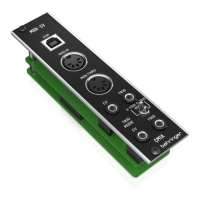
Power Connection
The 961 INTERFACE module comes with the required power cable
for connecting to a standard Eurorack power supply system.
Follow these steps to connect power to the module. It is easier to
make these connections before the module has been mounted
into a rack case.
1. Turn the power supply or rack case power o and
disconnect the power cable.
2. Insert the 16-pin connector on the power cable into the
socket on the power supply or rack case. The connector has
a tab that will align with the gap in the socket, so it cannot
be inserted incorrectly. If the power supply does not have
a keyed socket, be sure to orient pin 1 (-12 V) with the red
stripe on the cable.
3. Insert the 10-pin connector into the socket on the back of
the module. The connector has a tab that will align with the
socket for correct orientation.
4. After both ends of the power cable have been securely
attached, you may mount the module in a case and turn on
the power supply.
(1) (2) (4)
(5)
(7)
(6)
(8)
(3)