12 13MULTIGATE PRO XR4400 Quick Start Guide
MULTIGATE PRO XR4400 Controls
BEHRINGER
MULTIGATE PRO
MODEL XR4400
CONCEIV ED AND DESIGNED B Y
BEHRINGER GERMANY.
MADE IN CHINA.
ALL INPU TS & OUTPUT S
FULLY BALANCED
TIP
/
PIN 2
RING
/
PIN 3
SLEEVE
/
PIN 1
ALL INPU TS & OUTPUT S
FULLY BALANCED
TIP
/
PIN 2
RING
/
PIN 3
SLEEVE
/
PIN 1
ALL INPUTS & OUTPUTS
FULLY BALANCED
TIP
/
PIN 2
RING
/
PIN 3
SLEEVE
/
PIN 1
ALL INPUTS & OUTPUTS
FULLY BALANCED
TIP
/
PIN 2
RING
/
PIN 3
SLEEVE
/
PIN 1
INPUT S 4OUTPUTS 4 0UTPUTS 3 INPUT S 3 0UTPUTS 2 INPUTS 2 0UTPUTS 1 INPUTS 1
(1) (3)
(4)
(7) (8) (10)
(12)
(13)
(14) (15)(16)
(6) (11)
(2) (5) (9)
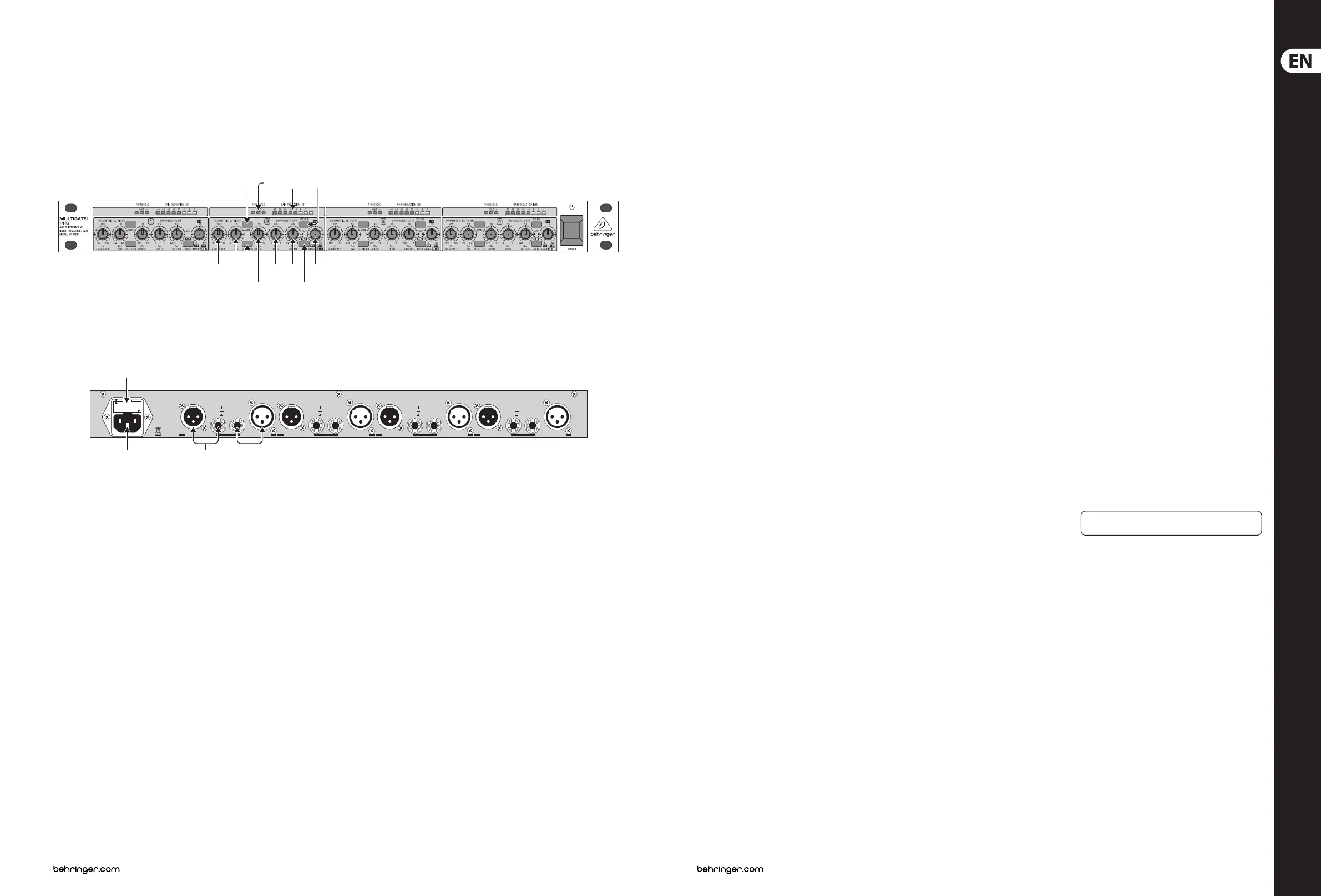
(EN) Controls
(1) The FREQUENCY control determines the
lower limit frequency of the sidechain lter,
and covers a range from 100 Hz to 10 kHz.
(2) The BANDWIDTH control determines the
slope or bandwidth of the sidechain lter.
The bandwidth can be set within a range
from 2.3 to 0.7octaves, so as to realize even
extremely narrow-band lter settings.
(3) The FILTER control activates the parametric
sidechain lter. To edit this lter there you
can use the frequency and BW control.
(4) The MONITOR switch establishes a link
between the sidechain control signal and
the audio output. As it also mutes the audio
input signal the user can pre-monitor the
parametric lter output, which makes it
easier to tune the lter by ear.
(5) Use the THRESHOLD control to set the
threshold point of the expander/gate
function within a range from BYPASS to
+10 dBu. Signals below the threshold are
reduced in level. When the signal drops
below the threshold, the hold/release
function starts reducing the signal to a level
adjustable with the RANGE/RATIO control.
(6) This “trac light” LED chain shows the
current operating mode of the unit:
the“+”LED (red) indicates that the sidechain
signal is below the threshold, theHOLD
LED (yellow) informs you that the hold
circuit/release process has been activated,
whilethe “-” LED (green) showsthat the
sidechain signal is above thethreshold.
(7) The HOLD control determines the delay
applied to the starting point of the release
process, after the signal has dropped below
the threshold. Thesetting range is 0 to
4seconds.
(8) The RELEASE control determines the time of
the release process. Thisprocess begins after
the end of the hold phase and ends when
the gain reduction adjusted with the RANGE
control is achieved. The setting range of the
RELEASE control is from 0.05 to 4 seconds.
(9) The MODE switch is used to set the
operating mode of the respective channel.
When the switch is out, the corresponding
section works as an ultra-fast gate. Inthis
mode, even percussive signals can be
processed without any signal loss. Withthe
MODE function on, the IRC expander
(Interactive Ratio Control) is activated.
Thisinteractive control function allows
for the program-dependent expansion of
complex signals.
(10) The RANGE/RATIO control performs a
dual function: depending on the position
of the MODE switch (i.e. depending on
the operating mode of the unit: gate or
expander), the RANGE/RATIO control
determines the maximum amount of gain
reduction or the expansion curve. In gate
mode, this control adjusts the RANGE
determining the amount of maximum gain
reduction from 0 dB to -80 dB. In expander
mode, it works as a RATIO control setting
the expansion ratio. The ratio function
determines the input vs. output level
ratio, for all signals below the threshold.
Thesetting range is from 1:1 to 1:4.
(11) The 8-digit GAIN REDUCTION meter
informs you about the current amount
of gain reduction within a range from
1to40dB.
(12) When you press the COUPLE switch,
thischannel is automatically congured as
a “slave” channel. Its left neighbor becomes
the “master” now controlling both channels
in all their parameters.
(13) FUSE HOLDER / VOLTAGE SELECTOR.
(14) MAINS CONNECTION.
(15) AUDIO IN.
(16) AUDIO OUT.
Check Out behringer.com for Full Manual