6
SHARK DSP110
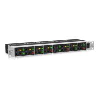
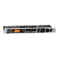
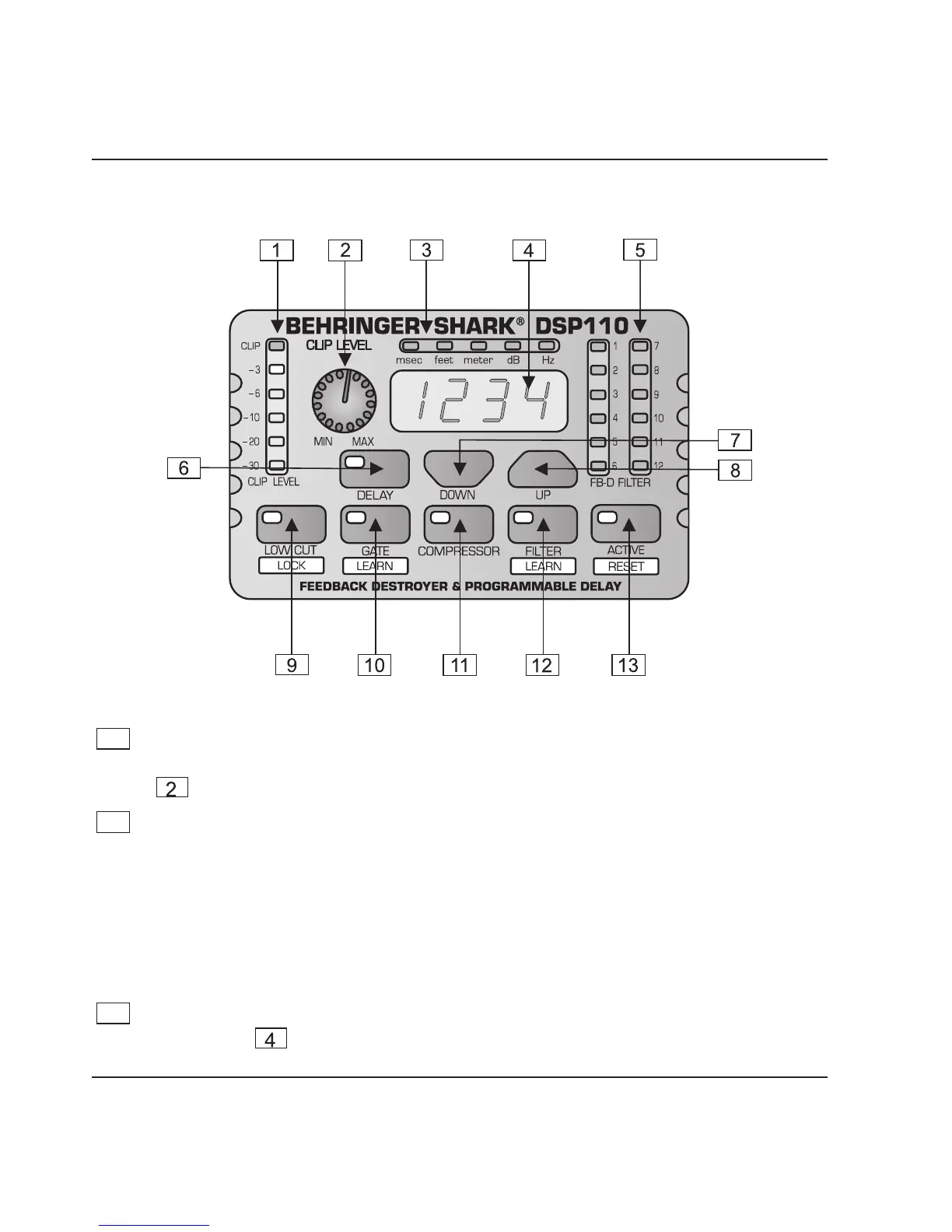
1.3 Control elements
Fig. 1.2: Front panel control elements of the DSP110
1
The CLIP LEVEL METER shows you whether or not the digital circuitry is
driven correctly. Any corrections can be made with the CLIP LEVEL control
. Be sure that the CLIP LED wont light up.
2
The CLIP LEVEL control lets you adapt the internal gain optimally to the digital
circuitry. If gain is too high (CLIP LED lights up), raise the CLIP LEVEL value by
turning the control to the right (and vice versa). Thus, you can shift the operating
level upwards/downwards.
+ The CLIP LEVEL control does not affect the input/output levels, but adapts
the audio signal as optimally as possible to the threshold of the digital
circuitry.
3
These five LEDs symbolize the units of the parameters that can be adjusted on
the display
.
1. INTRODUCTION
 Loading...