Quick Start Guide 15
Mains
(18) POWER: The POWER switch powers up the
mixer. The POWER switch should be in the
O position when connecting the unit to
themains.
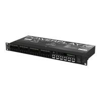
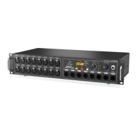
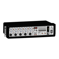
Rear Panel
The BUS LINKS connector as well as the channel
inputs 7 and 8 are unbalanced. The other PCB
inputs and outputs are balanced. To use balanced
connectors for unbalanced connections, insert a
jumper wire between the ground pin (m) and the
negative pin (-).
(19) IEC power receptacle: Theconnection to the
mains is established through an IEC connector.
It meets all of the international safety
certication requirements. A tting power
cord is included.
(20) REMOTE: This connector is used for
connecting components to remote control
theZMX8210.
• It is possible to connect a simple potentiometer to
remote control the volume of the LEFT and RIGHT
buses (seeChapter 3.1.3).
• Connect a push-button switch and two control
diodes to remote control the CHSELECT switch (10)
of channels 7 and 8 (see Chapter 3.1.3).
(21) BUS LINKS: Use this connector to link two
ZMX8210s together to provide additional
inputs (signals). The three output buses
LEFT/RIGHT/AUX are linked together using
the connector. The mute signal of the
ZMX8210 which is set to be the master is also
transmitted so that the mute function of
the master is also able to mute the buses of
theslave.
(22) SLAVE/MASTER: The switch places the
ZMX8210 in the master or slave mode
ofoperation.
When the switch
• is pressed, the ZMX8210 is placed in the slave
mode of operation.
• is not pressed, the ZMX8210 is placed in the
master mode ofoperation.
(23) AUX/OUT R/OUT L: Balanced signal outputs
for buses AUX, RIGHT and LEFT.
(24) INPUTS 7 – 8: Unbalanced signal inputs
for channels 7 – 8. Theconnections are
RCAconnectors.
(25) INPUTS 1 – 6: Balanced signal inputs for
channels 1 – 6.

 Loading...