12
XENYX 1222FX
+ Connect microphones before you switch on the
phantom power supply. Please do not connect
microphones to the mixer (or the stagebox/
wallbox) while the phantom power supply is
switched on. In addition, the monitor/PA
loudspeakers should be muted before you activate
the phantom power supply. After switching on,
wait approx. one minute to allow for system
stabilization.
+ Caution! You must never use unbalanced XLR
connectors (PIN 1 and 3 connected) on the MIC
input connectors if you want to use the phantom
power supply.
SERIAL NUMBER
Please note the important information on the serial number
given in chapter 1.3.3.
3. DIGITAL EFFECTS PROCESSOR
AND XPQ SURROUND FUNCTION
3.1 Digital effects processor
Fig. 3.1: Effects presets overview
24-BIT MULTI-EFFECTS PROCESSOR
Here you can find a list of all presets stored in the multi-effects
processor. This built-in effects module produces high-grade
standard effects such as reverb, chorus, flanger, delay and
various combination effects. The integrated effects module has
the advantage of requiring no wiring. This way, the danger of
creating ground loops or uneven signal levels is eliminated at the
outset, completely simplifying the handling.
These effect presets are designed to be added to dry signals.
If you move the FX TO MAIN control, you mix the channel signal
(dry) and the effect signal.
This also goes for mixing effects signals with the monitor mix.
The main difference is that the mix ratio is adjusted using the
FX TO MON control. Of course, a signal has to be fed into the
effects processor via the FX control in the channel strip for both
applications.
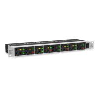
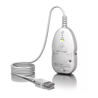
Fig. 3.2: Connection socket for the footswitch
FOOTSWITCH
Connect a standard footswitch to the footswitch connector;
use this to switch the effects processor on and off. A flashing
dot at the bottom of the display indicates if the effects processor
is muted via the footswitch.
+ In chapter 4.2, you will find an illustration showing
how to connect your footswitch correctly.
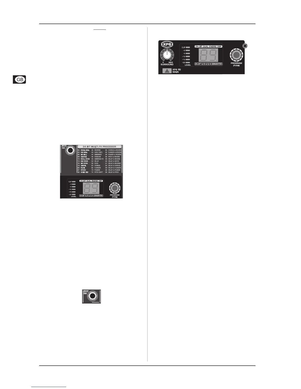
Fig. 3.3: Digital Effects module and
XPQ Surround Function control elements
LEVEL
The LED level meter on the effects module should display a
sufficiently high level. Take care to ensure that the clip LED only
lights up at peak levels. If it is lit constantly, you are overloading
the effects processor and this could cause unpleasant distortion.
The FX SEND fader determines the level that reaches the effects
module.
PROGRAM
You can select the effect preset by turning the PROGRAM
control. The display flashes the number of the current preset. To
recall the selected preset, press the button; the flashing stops.
You can also recall the selected preset using the footswitch.
3.2 XPQ surround function
The surround function can be enabled/disabled with the
XPQTOMAIN switch. This is a built-in effect that widens the
stereo width, thus making the sound more lively and transparent.
Use the SURROUND control to determine the intensity of this
effect.
4. INSTALLATION
4.1 Rack mounting
The packaging of your mixing console contains two 19" rack
mount brackets which can be installed on the side panels of the
console.
Before you can attach the rack mount brackets to the mixing
console, you need to remove the screws holding the left and
right side panels. Use these screws to fasten the two brackets
onto the console, being careful to note that each bracket fits a
specific side. With the rack mount brackets installed, you can
mount the mixing console in a commercially available 19" rack.
Be sure to allow for proper air flow around the unit, and do not
place the mixing console close to radiators or power amps, so
as to avoid overheating.
+ Only use the screws holding the mixing console
side panels to fasten the 19" rack mounts.
4.2 Cable connections
You will need a large number of cables for the various
connections to and from the console. The following illustrations
show the wiring of these cables. Be sure to use only high-grade
cables.
4. INSTALLATION

 Loading...