Installation
3.
Make sure that the mounting surface of the cutout is smooth and cleaned from
any burrs or debris.
4.
Install the operator panel into the cutout.
5.
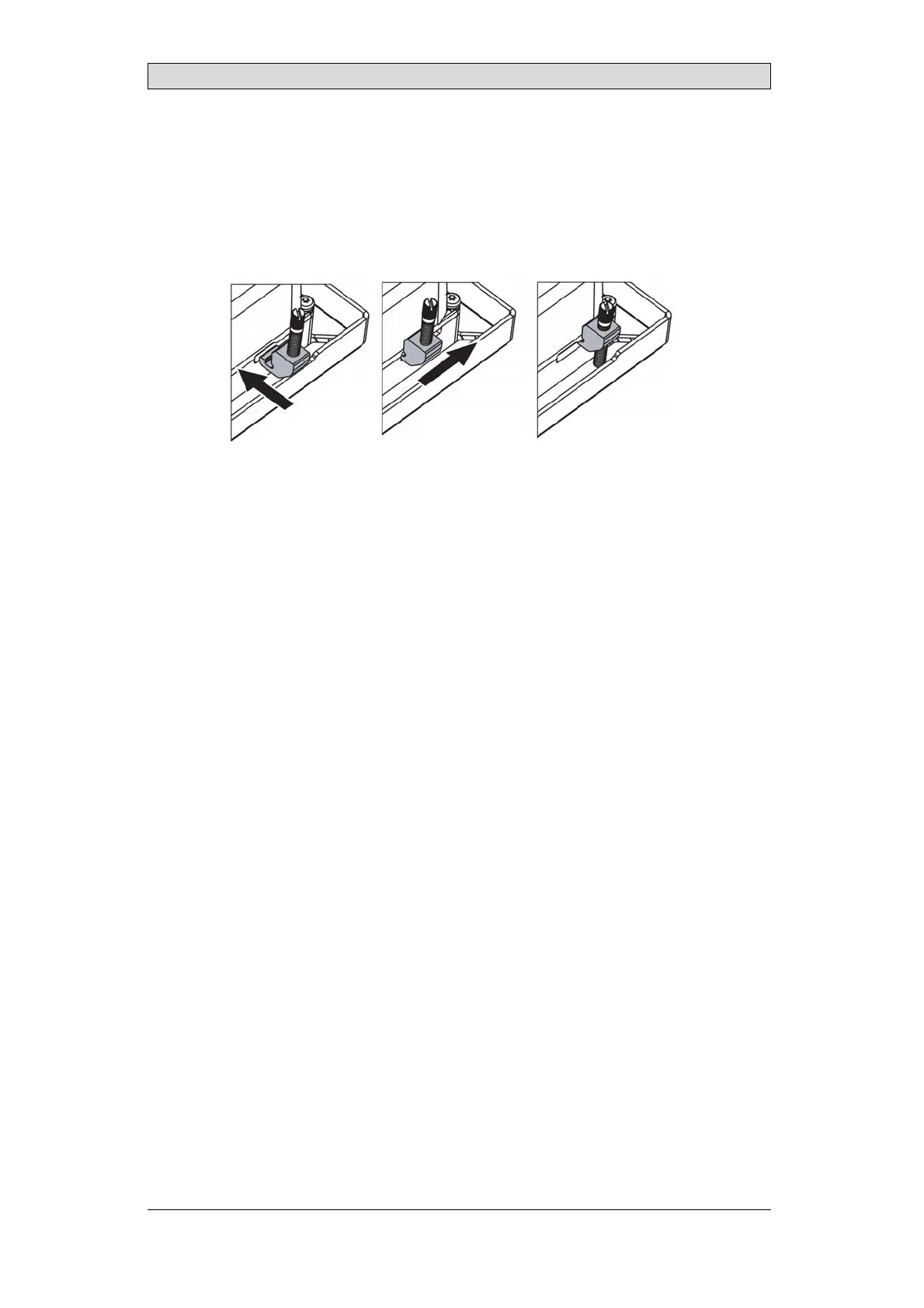
Secure the operator panel in position by inser ting and sliding the terminal
mounting clips into position as shown. Screw the slotted thumb screws
clockwise, allowing the screws to tighten against the cabinet.
Tighten the screws to 0.7 Nm ± 0.2 Nm.
6.
In cases where the front panel seal is critical, install terminal mounting
ring and use a torque wrench to ensure all screws are torqued within the
specification above. For IP66 UL/NEMA Type 4X, Type12, panel must
maintain a flatness < 1 mm overall and < 0.05 mm/mm with a surface
roughness, Ra < 1.6 μm
7.
Installation to be through an EPL (Db)(Dc) enclosure for the applicable Dust
Group, Temperature classification and Amb ient temperature range.
BeijerElectronics, MAEN249B
12
 Loading...