C-3
A1SJ71C24-R4/A1SJ71UC24-R4/A1SJ71C24-R2/A1SJ71UC24-
R2
Station number:
When communicating with the E-series: 0
Mode setting:
When communicating with the E-series:
A1SJ71C24-R4/A1SJ71UC24-R4: 5
A1SJ71C24-R2/A1SJ71UC24-R2: 1
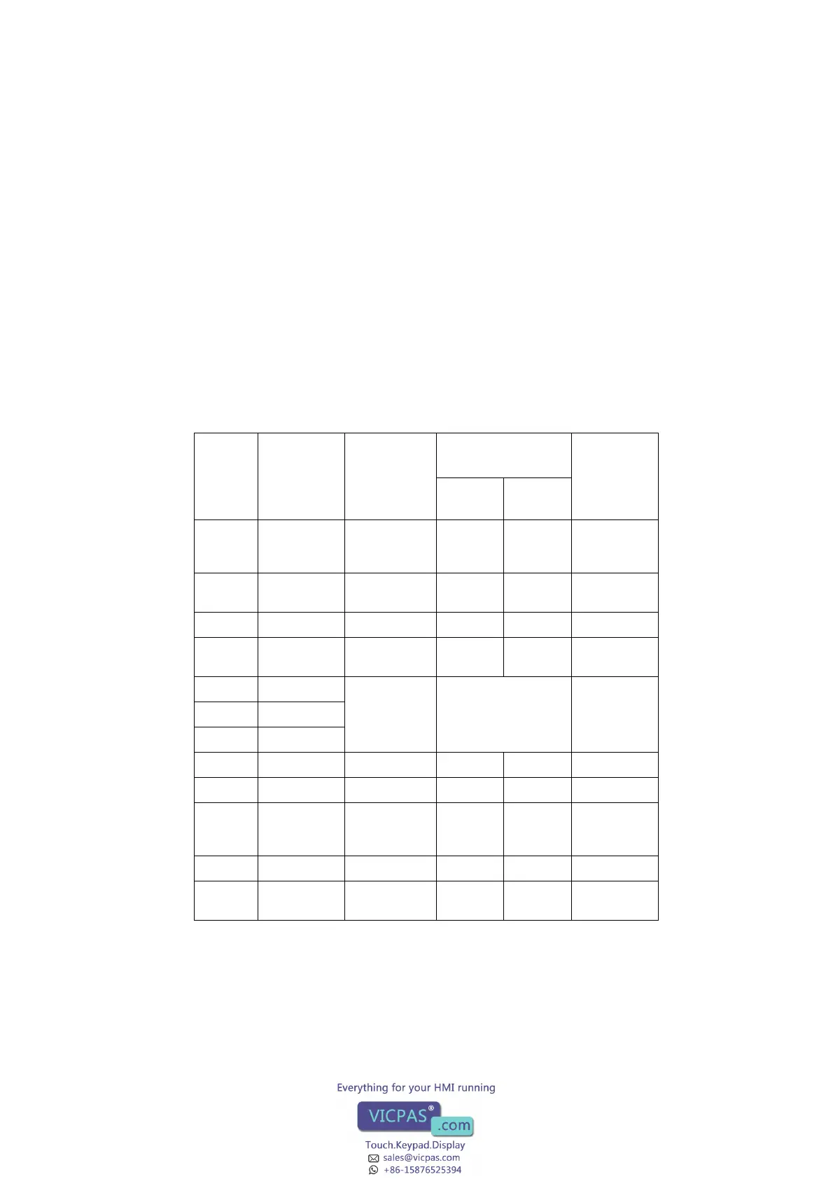
Setting of the switches:
Switch
Default
comm.
settings in
software to
E-series
Setting items
Position of Setting
Switch
Notes
ON OFF
SW01
Only -R4
OFF Main drop set-
tings
Master
station
Local sta-
tion
Valid only
when SW2 is
OFF
SW02
Only -R4
ON Computer link/
Multidrop
Com-
puter link
Multidrop
link
Must be ON
SW03 OFF Unused – – –
SW04 ON Write during
RUN
Enabled Disabled For dedi-
cated protocol
SW05 OFF Transmission
speed setting
Refer to the table below –
SW06 ON
SW07 ON
SW08 ON Data length 8 bits 7 bits –
SW09 OFF Parity check Enabled Disabled –
SW10 OFF Parity setting Even Odd Valid only
when SW09
is ON
SW11 OFF Stop bit 2 bits 1 bit –
SW12 ON Sum check Enabled Disabled For dedi-
cated protocol