Installation
4.
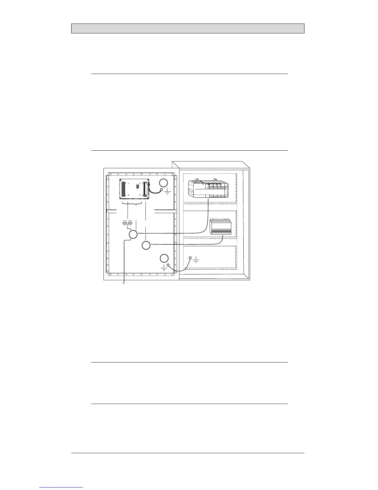
Connect the cables in the specified order, according to the drawing and steps
below.
Caution:
• Ensurethattheoperatorpanelandthecontrollersystemhavethesameelectrical
grounding(referencevoltagelevel),otherwiseerrorsincommunicationmay
occur.
• Theoperatorpanelmustbebroughttoambienttemperaturebeforeitisstarted
up. Ifcondensationforms,ensurethattheoperatorpanelisdrybeforeconnecting
ittothepoweroutlet.
• Ensurethatthevoltageandpolarityofthepowersourceiscorrect.
• Useonlyshieldedcommunicationcables.
• Separatehighvoltagecablesfromsignalandsupplycables.
24V DC
RS232/
RS422/
RS485
24V DC
A
D
Controller
Power
B
Ethernet
C
– Connect cable A.
– Connect cable B, using an M5 screw and a grounding conductor (as short
as possible) with a cross-section of minimum 2.5 mm
2
.
– Connect cable C.
– Connect cable D.
5.
Carefully remove the laminated film over the operator panel display, to avoid
static electricity that could damage the panel.
Note:
Whenconnectingtheoperatorpaneltothepoweroutletforthefirsttime,make
surenottointerruptpowerforaminimumof48hoursinordertochargethebattery
completely. Aft erthat,thebatterymaybechargedpartlyduringashorterperiodof
time.
BeijerElectronics, MAEN015A
8