Do you have a question about the Belanger Top Winder and is the answer not in the manual?
Details the warranty period for the equipment itself.
Specifies the warranty coverage for replacement parts.
Outlines conditions that void warranties and specific exclusions.
States that this warranty is in lieu of all other express or implied warranties.
Lists dangerous chemicals and notes warranty voiding for their use.
Advises on tightening electrical panel connections during installation.
Explanation of hazard symbols and signal words used in the manual.
Emphasizes reading the manual and using trained personnel for installation.
Crucial warning to disconnect power before servicing equipment.
General description of the TopWinder and its main function.
Lists tools needed and equipment included for installation.
Details tunnel space, height, width, electrical, pneumatic, and water needs.
Specifies vehicle clearance height.
Safety notes for electrical, hydraulic, and air systems.
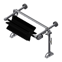
Illustrates the overall dimensions of the TopWinder unit.
Instructions for assembling the main frame structure.
Positioning the driver and passenger side arm assemblies.
Steps for securing the crossbeam to the arm assemblies.
Instructions for connecting the leg assemblies to the arms.
Identifying conveyor guide rails for correct TopWinder positioning.
Correct side-to-side placement instructions within the tunnel.
Procedures for standing the frame upright and securing it.
Securing the shock assemblies to the leg and arm components.
Introduction to the auto-retract sensor system.
Steps for mounting the photo-eye sensors.
Details electrical connections for the auto-retract.
Installing the retract cylinder and air cushion regulator.
Trimming and securing filler strips on leg assemblies.
Mounting the air panel and connecting pneumatic lines.
Procedures and considerations for installing counterweights.
Steps for installing the drive shaft and hub assembly.
Instructions for fitting the ShineMitt™ cleaning material.
Steps to connect the motor and slip ring to the drive shaft.
Routing electrical cables for the motor and LED lights.
Securing the water line and bundling electrical/pneumatic lines.
Methods to check and adjust the wheel's rotation speed.
Checking wheel penetration using a fish scale.
Adjusting air pressure for the retract cylinder's operation.
Includes flushing, nozzle installation, and test vehicle runs.
Daily, weekly, and monthly tasks for upkeep.
Importance and procedure for cleaning the powder coated surfaces.
Techniques for repairing fading, scratches, and paint application.
Step-by-step guide for replacing the hub's LED lights.
Procedures for removing and replacing motor and torque plate components.
Detailed diagrams of various assemblies and components.
Diagrams showing components of the driver side leg assembly.
Diagrams showing components of the passenger side leg assembly.
Diagrams showing components of the driver side arm assembly.
Diagrams showing components of the passenger side arm assembly.
Diagrams showing components of the crossbeam assembly.
Diagrams showing components related to counterweights.
Diagrams showing components of the hub and shaft assembly.
Diagrams showing components of the motor drive assembly.
Diagrams showing the slip ring to wire harness cable.
Diagrams showing ShineMitt™ fill patterns and replacement.
Diagrams showing the air cushion regulator assembly.
Diagrams showing the retract assembly with photo-eye set.
Diagrams showing the retract air panel components.
| Type | Top Winder |
|---|---|
| Category | Racks & Stands |
| Material | Steel |
| Color | Black |
| Weight Capacity | 100 lbs |