Do you have a question about the BELIMED WD230 and is the answer not in the manual?
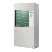
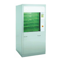
Technical specifications and components of the WD 230/250 machines.
Details of water and drain connections for the machine.
Electrical connection requirements for different regions.
Description of input modules and their functions within the service module.
Explanation of the general key functions available on the service module.
Details on user roles and their access levels to machine functions.
Procedure for accessing the machine's service module.
Methods for opening both the unclean and clean side doors.
Summary of the different service modules and their capabilities.
Module for analyzing operating conditions and current values.
Displays actual readings from the temperature sensors.
Displays actual readings from the level sensors.
Mode suitable for validating dosing quantities.
Module for configuration by detergent manufacturers.
Configuration for mixing and simultaneous dosing of multiple units.
Procedure for calibrating the dosing pump based on time.
Procedure for calibrating the flow meters using impulse counts.
Module for direct manual control of machine outputs.
Module for adjusting process parameters and programs.
General overview of parameter input for program settings.
Details on using cold water within the cycle.
Details on using warm water within the cycle.
Details on using mixed cold and warm water.
Details on using de-mineralized water in the cycle.
Details on the hot air drying process.
Details on the operation of the condenser.
Details on using pre-heated DI water for final rinsing.
How to deactivate a specific program step.
Explanation of indicator functions within the program.
Functions for thermal or chemical disinfection processes.
Thermal disinfection process with a specific Ao value.
Thermal disinfection process with a different Ao value.
User-configurable program steps with empty functions.
Module for configuring machine setup and operating modes.
Setting the timer for automatic self-disinfection.
Configuration of maintenance alerts and service intervals.
Setting the machine name for documentation purposes.
Setting parameters related to door pressure.
Liquid drainage suppression based on infection protection law.
Automatic program selection based on basket coding.
How error messages are displayed on the machine.
Setting for automatic CS door opening after program completion.
Configuration of the door interlock for the unclean side.
Setting up user identification for batch documentation.
Automatic identification of wash racks using keypad or scanner.
Enabling or disabling batch content identification.
List of machine outputs and their corresponding codes.
Function of the external load cut-off input.
Function of the leakage floor pan input.
Function of the DI boiler code input.
Function of the DI boiler float switch.
Connection and configuration for the Bach documentation system.
Summary of interface options for external communication devices.
General steps for diagnosing and addressing machine malfunctions.
Color coding scheme for low voltage wiring circuits.
Detailed table of error codes, their causes, and remedies.
Information regarding the duration of various process cycles.
Details on water and energy consumption of the machine.
Validated process parameters for programs P1 through P7.
Information on assigning different media to program steps.
Diagram illustrating the function of the dosing system.
| Brand | BELIMED |
|---|---|
| Model | WD230 |
| Category | Racks & Stands |
| Language | English |