800-543-9038 USA 866-805-7089 CANADA 203-791-8396 LATIN AMERICA / CARIBBEAN
4
FB24-MFT N4
H
, AFB24-MFT-S N4
H
, AFX24-MFT N4, AFX24-MFT-S N
EMA 4, Proportional,
pring Return, Direct
oupled, 24V, Multi-Function Technolog
399_08
D
4-2
mA
W399_08
399_08
399_08
loatin
Point Contro
K-AF-NF N4H 24V h
t
r
EMA 4 H
t
r
Accessories
oo
-0
mm an
10 mm wrenc
-
Gland
needed for additional wires
1
7-
1
asket for
land (needed for additional wires
N
TE
When using AFB24-MFT N4(H), AFB24-MFT-S N4(H), AFX24-MFT N4 and AFX24-MFT-S N
ctuators, only use accessories listed on this page.
For actuator wirin
information and dia
rams, refer to Belimo Wirin
uide
Typical Specification
pring return control damper actuators shall be direct coupled type which require no
rank arm and linka
e and be capable of direct mountin
to a
ackshaft up to a 1.05”
ameter.
e actuator must prov
e proport
ona
amper contro
n response to a 2 to
10 VD
or
with the addition of a 50
resistor, a 4 to 20 mA control in
ut from an
ectron
c contro
er or pos
t
oner.
e actuators must
e
es
gne
so t
at t
ey may
e
sed for either clockwise or counterclockwise fail-safe operation. Actuators shall use
a brushless D
motor controlled b
a micro
rocessor and be
rotected from overload
at all angles of rotation. Run time shall be constant, and independent of torque. A 2 to
10 VD
feedback signal shall be provided for position feedback. Actuators shall be
ULus Approved and have a 5 year warranty, and be manufactured under I
9001
International
ualit
ontrol
tandards. Actuators shall be as manufactured b
Belimo.
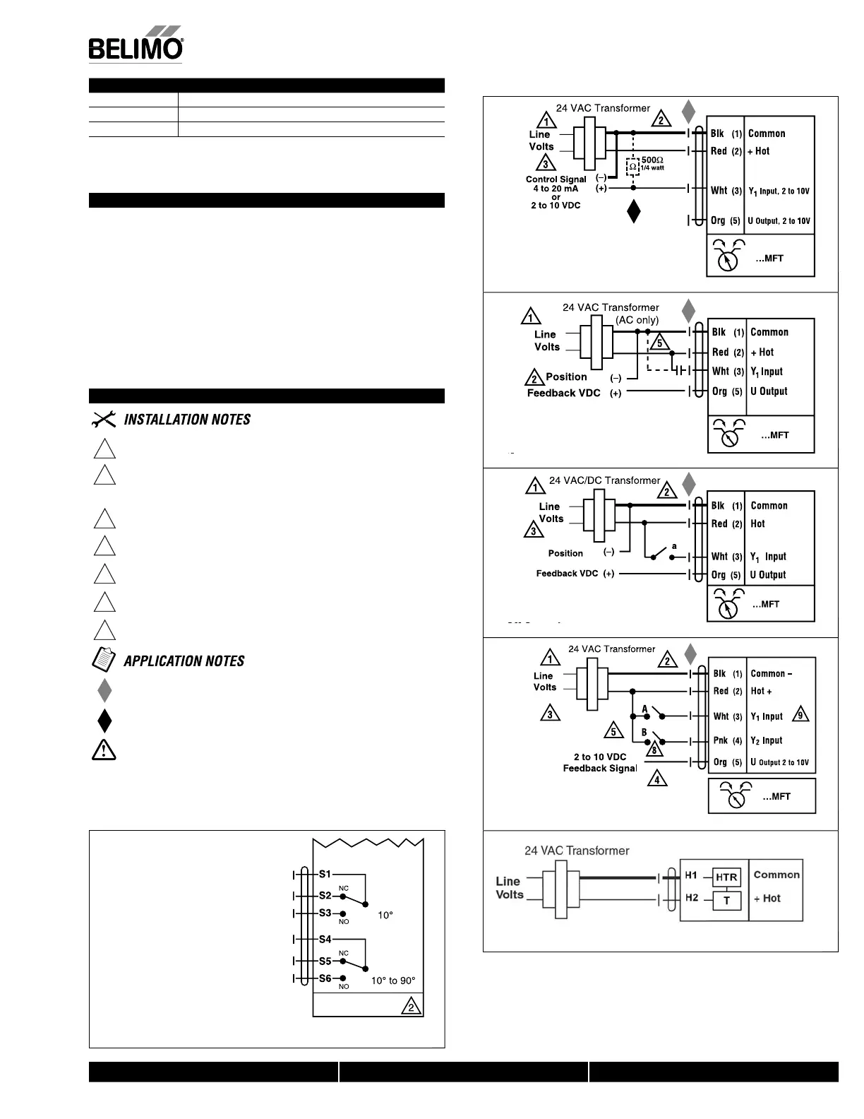
Wiring Diagrams
1
rovide overload protection and disconnect as required
2
AUTI
N Equipment Dama
e
Actuators ma
be connected in
arallel if not mechanicall
mounted to the same
shaft. Power consum
tion and in
ut im
edance must be observed.
Actuators may also be powered by 24 VDC.
osition feedback cannot be used with Triac sink controller.
he actuator internal common reference is not com
atible.
ontrol signal may be pulsed from either the Hot (source) or the
ommon
sink) 24 VA
line
ontact closures A & B also can be triacs
A & B should both be closed
or triac source and open
or triac sink
r tri
ink th
mm
n
nn
ti
n fr
m th
t
t
r m
t
nn
t
t
th
h
t
nn
ti
n
f th
ntr
ll
r.
Meets UL requirements without the need o
an electrical ground
connect
on
h
Z
-R
1
Ω resistor ma
be used.
ARNIN
Live Electrical Com
onents
ur
ng installation, testing, servicing and troubleshooting o
this product, it may be
necessar
to work with live electrical com
onents. Have a
uali
ed licensed electrician
or ot
er
n
v
ua
w
o
as
een proper
y tra
ne
n
an
ng
ve e
ectr
ca
components
perform these tasks. Failure to follow all electrical safety precautions when exposed to
live electrical components could result in death or serious in
ury
AFB24-MFT-S N4(H)
AFX24-MFT-S N4
Auxiliary
witches
600
N40103 - 09/11 - Subject to change. © Belimo Aircontrols (USA), Inc.
 Loading...


