800-543-9038 USA 866-805-7089 CANADA 203-791-8396 LATIN AMERICA / CARIBBEAN
AFB24-MFT95, AFX24-MFT95
roportional, Sprin
Return, 24 V, for Use with Honeywel
®
Electronic Series 90 or a 0 to 135
n
u
• Torque m
n. 180
n-l
• Control fixed, 0 to 135
input, or Honeywell series 90 (fixed
• Feedback 2 to 10 VD
DEFAULT
A
l
cat
o
or proportional modulation of dampers and control valves in HVA
systems. The
AFB24-MFT95, AFX24-MFT95 provides mechanical spring return operation for reliable
fail-safe a
lication.
efault/Configuratio
efault
arameters for 0 to 135
In
ut a
lications of the AFB24-MFT95 and AFX24
MFT95 actuator are assi
ned durin
manufacturin
. If required, custom versions of the
actuator can be ordered. However the control in
ut cannot be modified via MFT PC
tool software. The
arameters noted in the Technical Data table are variable.
ese parameters can
e c
ange
y t
ree means
Pre-set confi
urations from Belimo
ustom configurations from Belimo
Confi
urations set by the customer usin
the MFT PC tool
version 3.4 or hi
her
oftware a
lication
eratio
he AFB24-MFT95, AFX24-MFT95 actuator provides 95° o
rotation and is provided
ith a
raduated position indicator showin
0° to 95°. The actuator will synchronize
t
e 0° mec
an
ca
stop or t
e p
ys
ca
amper or va
ve mec
an
ca
stop an
use t
s
point for its zero position during normal control operations. A unique manual override
allows the setting of any actuator position within its 95° of rotation with no power
applied.This mechanism can be released physically by the use o
a crank supplied
ith the actuator. When power is applied the manual override is released and the
actuator drives toward the fail-safe position.
he actuator uses a brushless D
motor which is controlled by an Application
pecific
nte
rated Circuit
ASIC
and a microprocessor. The microprocessor provides the
intelli
ence to the ASIC to provide a constant rotation rate and to know the actuator’s
exact
osition. The ASIC monitors and controls the brushless DC motor’s rotation and
provides a Digital Rotation
ensing (DR
) function to prevent damage to the actuator
in a stall condition. The position
eedback signal is generated without the need
or
mechanical feedback potentiometers usin
DRS. The actuator may be stalled
an
where in its normal rotation without the need of mechanical end switches.
he AFB24-MFT95, AFX24-MFT95 is mounted directly to control sha
ts up to 1.05"
diameter by means of its universal clamp and anti-rotation bracket. A crank arm and
everal mounting brackets are available for damper applications where the actuator
cannot be direct coupled to the damper sha
t. The sprin
return system provides
minimum speci
ied torque to the application durin
a power interruption. The AFB24-
MFT95, AFX24-MFT95 actuator is shipped at +5°
5° from full fail-safe
to provide
automatic compression a
ainst damper
askets
or ti
ht shut-o
Technical Data AFB24-MFT95, AFX24-MFT95
Power supply 24 VA
+
- 20%
50
60 H
24 VDC
+20% / -10%
Power
consum
t
o
runnin
7.5 W
holdin
3 W
Trans
ormer sizin
10 VA
Class 2 power source
tr
nn
t
24-
95 3 ft, 18 GA plenum cable
with 1
2”
n
it
nn
t
r
24-
3 ft
1m
, 18
A plenum cable
with or without 1
2” conduit connecto
verload protectio
electronic throughout 0 to 95° rotatio
Operatin
ran
e Y
to
5
Honeywell Electronic Series 90,
0 to 135
input
Feedback output U
2 to 10 VDC, 0.5 mA ma
orque
n
mum 180
n-
20
m
r
t
f r
t
ti
n*
spr
n
reversible with cw/ccw mountin
motor revers
e w
t
u
t-
n sw
tc
ec
an
ca
an
le o
rotation
95°
a
usta
e w
t
mec
an
ca
en
stop, 35° to 95°
Running time sprin
<20 seconds
-4°F to 122°F [-20°
to 50°
];
<60 seconds
-22°F [-30°
m
t
r
150 seconds
default
, variable
70 to 220 seconds
An
le o
Rotation
a
a
tat
on
o
de
ault
P
iti
n in
i
ti
visual indicator, 0° to 95
(0° is spring return position
anua
overr
e 5 mm
ex cran
₁₆
en
, supp
e
Humidit
ax. 95% RH, non-condensin
m
ent temperatur
-22 to 122° F
-30 to 50°
tora
e temperature -40 to 176° F
-40 to 80°
Housin
NEMA 2, IP54, Enclosure Type
Housin
material zinc coated metal and plastic casin
Noise leve
0dB
A
motor @ 150 seconds, run time dependen
2dB
A
sprin
return
A
ency listin
s † cULus acc. to UL60730-1A/-2-14, CAN/CSA E60730
1:02
CE acc. to 2004/108/EC & 2006/95/EC
Qualit
standard I
1
ervicing
int
n
n
r
e
g
4.6
s.
1.9
g
Variable when con
igured with MFT options
† Rated Impulse Volta
e 800V, Type of action 1.AA
1.AA.B for -
version
,
ontrol Pollution De
ree 3.
Programmed for 70 seconds motor run time. At 150 sec motor run time, transformer sizing is 8.5 V
nd power consumption is 6 W running / 3 W holding
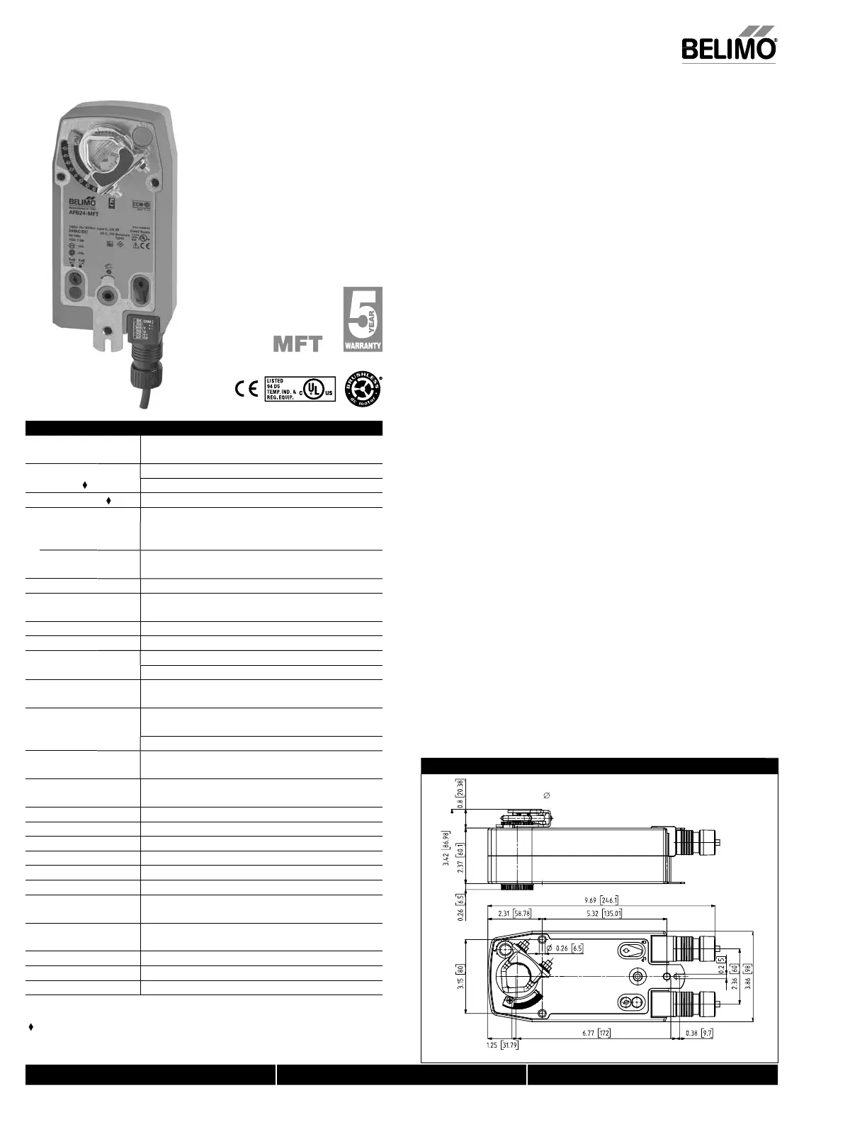
Dimensions (Inches [mm])
FBNFBDim
K7-2 (supplied)
1/2" Centered
(Default)
3/4" Centered
(Field Selectable)
1.05" Centered
(Field Selectable)
N40103 - 09/11 - Subject to change. © Belimo Aircontrols (USA), Inc
 Loading...


